background image

3 / 48

S1024.mz32_V1.7_sh_en

Table of contents

Intr

ŽĚƵĐƟŽŶ

 .............................................................................. 5

Service centre ............................................................................ 5

Intended use  ............................................................................. 6

Target group ....................................................................................6

Package content ........................................................................ 6

Technical data ............................................................................ 7

Symbol descrip

ƟŽŶ

 .................................................................... 7

Safety notes ............................................................................... 8

For your safety by handling the transmi

Ʃ

er ..................................8

For your safety! Handling the ba

Ʃ

ery. ...........................................9

Descrip

ƟŽŶŽĨƚŚĞƚ

ransmi

Ʃ

er ................................................. 11

Control elements on the transmi

Ʃ

er ...........................................11

Transmi

Ʃ

er Front ..........................................................................12

Transmi

Ʃ

er Backside.....................................................................13

ŽŶŶĞĐƟŽŶƐĂŶĚĮ

xtures ..............................................................14

A

Ʃ

aching the transmi

Ʃ

er neck-strap ........................................14

AUDIO c

ŽŶŶĞĐƟŽŶ

 .....................................................................14

DATA c

ŽŶŶĞĐƟŽŶ

 ........................................................................14

COM c

ŽŶŶĞĐƟŽŶ

 ........................................................................14

DSC c

ŽŶŶĞĐƟŽŶ

 ..........................................................................14

Micro USB c

ŽŶŶĞĐƟŽŶ

 ...............................................................14

Transmi

Ʃ

er prepara

ƟŽŶ

 ........................................................... 16

Control s

ƟĐŬ

 ..................................................................................16

Adjus

ƟŶŐƚŚĞůĞŶ

gth of the control s

ƟĐ

ks ..................................16

Neutralizing the control s

ƟĐ

ks ...................................................16

Brake spring and ratchet ............................................................16
Control s

ƟĐ

ks centering force ....................................................16

Transmi

Ʃ

er power supply .............................................................17

Installing the ba

Ʃ

ery ..................................................................17

Charge the ba

Ʃ

ery .....................................................................17

Removing the transmi

Ʃ

er ba

Ʃ

ery .............................................17

Low voltage warning ..................................................................17
Ba

Ʃ

er

LJƵƐĞƟŵĞƌ

 .......................................................................17

St

ĂƌƟŶŐƵƉƚŚĞƚ

ransmi

Ʃ

er ...................................................... 18

Switch on transmi

Ʃ

er ...................................................................18

/ŶŝƟĂůƐ

etup of the transmi

Ʃ

er .....................................................18

Switch o

īƚŚĞƚ

ransmi

Ʃ

er.............................................................21

hƐĞĂŶĚŵĞŶƵĨƵŶĐƟŽŶƐ

 .......................................................... 21

Opera

ƟŶŐƚŚĞĚŝƐƉů

ays ..................................................................21

Change current s

ƟĐŬŵŽĚĞ

 ...........................................................22

Содержание mz-32 HoTT

Страница 1: ...EN No S1024 77 32 channel 2 4 GHz transmiƩer mz 32 HoTT Manual EN C o p y r i g h t G r a u p n e r ...

Страница 2: ...2 48 S1024 mz32_V1 7_sh_en ...

Страница 3: ...k strap 14 AUDIO cŽŶŶĞĐƟŽŶ 14 DATA cŽŶŶĞĐƟŽŶ 14 COM cŽŶŶĞĐƟŽŶ 14 DSC cŽŶŶĞĐƟŽŶ 14 Micro USB cŽŶŶĞĐƟŽŶ 14 TransmiƩer preparaƟŽŶ 16 Control sƟĐŬ 16 AdjusƟŶŐ ƚŚĞ ůĞŶgth of the control sƟĐks 16 Neutralizing the control sƟĐks 16 Brake spring and ratchet 16 Control sƟĐks centering force 16 TransmiƩer power supply 17 Installing the baƩery 17 Charge the baƩery 17 Removing the transmiƩer baƩery 17 Low volt...

Страница 4: ...in display 25 Receiver Binding 26 Bind Group 26 Range test 27 Digital switch 28 SeƫŶŐ control and mixer characterisƟĐƐ 30 ƟĐŬ calibraƟŽŶ 32 Servo display 33 Telemetry 34 Select Rx 34 Telemetry Cycle 35 RF status 35 SETTING DATA VIEW 36 Digital switch 38 Firmware update 40 Forced update 42 SIMPLIFIED DECLARATION OF CONFORMITY 46 Notes on environmental protĞĐƟŽŶ 47 Care and maintenance 47 Warranty c...

Страница 5: ...d and follow this user manual and all the safety notes before using the product Note This manual is part of the product It contains important informa ƟŽŶ concerning operaƟŽŶ and handling Keep these insƚƌƵĐƟŽŶƐ for d e r r e f s n a r t u o y e s a c n i n o s r e p d r i h t o t t i e v i g d n a e c n e r e f e r e r u t u f the product Servic Center Graupner in Internet For the service centes ou...

Страница 6: ...must be followed in every case Note Read through this enƟre manual before you aƩempt to install or use the transmiƩer Target group The item is not a toy It is not suitable for children under 14 The operaƟŽŶ of the transmiƩer must be performed by experienced modelers If you do not have suĸĐŝĞnt knowledge about dealing with radio controlled models please contact an experienced mod eler or a model cl...

Страница 7: ...100 mA Dimensions Approx 210 x 195 x 105 mm Weight approx 1120g with baƩery Note The technical data of opƟŽŶĂůůLJ available receivers can be found in the related receiver system manual Symbol descripƟŽŶ Always observe the informaƟŽŶ indicated by this warning sign Par ƟĐƵůĂƌůLJ those which are ĂĚĚŝƟŽŶĂůůLJ marked with the words CAU TION or WARNING The signal word WARNING indicates the poten ƟĂů for se...

Страница 8: ...ibraƟŽŶ as well as excessive heat or cold The models may only be operated remotely in normal outside temperatures such as from 10 C to 55 C ͻ First always perform a range and ĨƵŶĐƟŽŶ test on the ground before you start using your model Only so you can grant a safe use ͻ Always use all your HoTT components only with the latest Įƌmware version ͻ If you have quesƟŽŶƐ which cannot be answered by the o...

Страница 9: ...he respec Ɵve cell type may not be exceeded ͻ If the baƩery heats up above 60 C while it is being charged stop charging and let the baƩery cool down to approximately 30 40 C ͻ Never charge baƩeries that have already been charged or hot ones If a cell in a baƩery pack has become ƉĂƌƟĐƵůĂƌůLJ hot fol lowing a quick charge process this may indicate a defect in that cell Do not use the baƩery pack any ...

Страница 10: ... 48 S1024 mz32_V1 7_sh_en they must be recharged immediately Deep discharge makes the baƩery short term longer storage in discharged as well as fully charged state make the baƩery in the long term useless ...

Страница 11: ...ol elements on the transmiƩer 1 3 way switch SW 5 2 2 way switch SW 6 3 Digital buƩon DT7 4 PrŽƉŽƌƟŽŶĂů ĚŝĂů DV3 5 Foldable transmiƩer antenna 6 TransmiƩer handle 7 PrŽƉŽƌƟŽŶĂů ĚŝĂů DV4 8 Digital buƩon DT8 9 3 way switch SW 8 top push switch boƩom latch ing switch 10 3 way switch SW 7 ...

Страница 12: ...Ŭ 6 LeŌ control sƟĐŬ 7 PrŽƉŽƌƟŽŶĂů ĚŝĂů DV1 8 3 way switch SW 1 9 3 way switch SW 8 1x push switch 2x latching switch 10 Digital buƩon DT5 11 Digital buƩon DT6 12 3 way switch SW 3 13 3 way switch SW 4 14 PrŽƉŽƌƟŽŶĂů ĚŝĂů DV2 15 Right control sƟĐŬ 16 Trim buƩon of the right control sƟĐŬ 17 Eyelet for transmiƩer strap 18 Direct recall of the servo display 19 Direct recall of the SETTING DATA VIEW 2...

Страница 13: ...control LV2 6 Inner screw adjusts brake force Outer screw adjusts ratchet s strength 7 TransmiƩer handle 8 Foldable transmiƩer antenna 9 CovĞƌ ŇĂƉ over audio COMM DATA and DSC cŽŶŶĞĐƟŽŶ 10 Inner screw adjusts brake force Outer screw adjusts ratchet s strength 11 PrŽƉŽƌƟŽŶĂů rotary control LV1 12 Gimbal tension screw for horizontal contrŽů ĨƵŶĐƟŽŶ 13 Gimbal tension screw for vĞƌƟcal control Lower s...

Страница 14: ... in the submenu I O conĮŐ Η of the system menu see below under DSC cŽŶŶĞĐƟŽŶ COM cŽŶŶĞĐƟŽŶ Serial interface for future use DSC cŽŶŶĞĐƟŽŶ Through a DSC cable this port can be used for a simulator or for Teacher Student mode If necessary switch to the required DSC operaƟŶŐ mode in the I O ConĮŐ Η ƐƵďŵĞŶƵ ŽĨ ƚŚĞ system menu To ensure a correct DSC cŽŶŶĞĐƟŽŶ Žbserve the following 1 Perform any necessa...

Страница 15: ...cess Only the red ŇĂƐŚ in the baƩery symbol in the upper right corner of the display indicates that the charging process is sƟůů ƌƵŶŶŝŶŐ WARNING The charger should always be supervised during charge and it should be used only in rŽŽŵƐ ĮƩed with a smoke detector Mass storage memory If the mz 32 HoTT transmiƩer is connected to a compaƟďůĞ PC and the Mass storage ĮĞůĚ is ĂĐƟvated by tapping the memor...

Страница 16: ...stop to stop or counterclockwise unƟů the con trol sƟĐŬ ŝƐ Ăgain self neutralizing Note Which of the two control sƟĐks is to be switched to non neutraliz ing also depends on the choice of the control mode see under Commissioning the transmiƩer Brake spring and ratchet On both control sƟĐks the braking force and strength of the ratchet can be adjusted independently Consult the transmiƩer backside d...

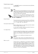
Страница 17: ... baƩery and then carefully remove the plugs of the power cable r u o y t l u s n o C r e t t i m s n a r t e h t e d i s t u o y r e t t a b e h t e g r a h c n a c u o Y charger insƚƌƵĐƟŽŶƐ for proper charging ow voltage warning The supply voltage of the transmiƩer must be monitored during operaƟŽŶ If it dropes below an adjustable capacity limit which by default is 20 an appropriate warning messa...

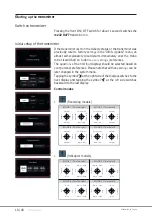
Страница 18: ...ŽŶƐ of the Įrst four displays should be selected based on your personal preferences Please note that all these seƫŶŐƐ can be later changed in the system menu Tapping the symbol at the right side of the display switches to the next display and tapping the symbol at the leŌ side switches backward to the last display Control modes ͻ Fixed wing models tvklGYGO G P l l y y m G t G x x m G t G y y l l h...

Страница 19: ... done in the Control Mode Preset opƟŽŶ of the System ConĮŐ Η Submenu of the system menu ͻ Within a model memory the control mode can be also changed at any ƟŵĞ in the last value ĮĞůĚ of the sub menu Model Type of the basic menu ͻ Depending on the choice of a control mode one of the two con trol sƟĐks may also need to be switched to non neutralizing see above under Neutralizing the control sƟĐŬΗ ͻ ...

Страница 20: ...ith the leŌ ƌŝŐht arrow keys on the radio InsƚƌƵĐƟŽŶƐ for creaƟŶŐ and modifying decks can be found in the help menu or by following our online video tutorials System help Accessing the context ƐĞŶƐŝƟve help is done in each menu by tapping the top right of the display If required such help pages can also be created and stored by the user in the appropriate directory To create your own help page you...

Страница 21: ... indicators of the six freely conĮŐƵrable main dis plays which are outlined in red top leŌ Note When the transmiƩer is on an insulaƟŶŐ surface e g on a wooden table do not tap too strong on the display The rĞƐƵůƟŶŐ largĞƌ ĮŶ ger surface on the screen can result in un responsive behavior of the screen Touching the Menu ĮĞůĚ at the boƩom right of the main display changes to the last tab of the four ...

Страница 22: ...ƟĐŬ DŽĚĞΗ ŝcon dŚĞ ƐĞůĞĐƟŽŶ ǁŝŶĚoǁ Η ƟĐŬ DŽĚĞΗ ǁŝůů ƐŚow 5 Select the desired sƟĐŬ mode or tap cancel to return to the previ ous display without changing the sƟĐŬ ŵŽĚĞ ChangĞ ƟĐŬ DŽĚĞ Wreset Change sƟĐŬ ŵŽĚĞ ƉƌĞƐet step by step 1 Tap the blue System menu tab 2 Tap the icon System Set in the tŽƉ ůĞŌ corner 3 Tap the Η ƟĐŬ Mode Preset ĮĞůĚ and select the new default sƟĐŬ mode for your transmiƩer New...

Страница 23: ...the plus sign and follow the next steps Delete model step by step 1 Tap the green Basic menu tab 2 Tap the Model List menu tab 3 In the No cŽůƵŵŶ touch the model number of the model to be deleted 4 Touch the BasŬet icon A safety dialog will be displayed 5 Tapping the OK buƩon will delete the model Tap Cancel to abort the deletĞ ŽƉĞƌĂƟŽŶ Note The currently ĂĐƟve model cannot be deleted To delete th...

Страница 24: ...screen is ĂĐƟvated by pressing the two lower ƐĞůĞĐƟŽŶ keys simultaneously for approx 1 second ͻ The keLJ ůŽĐŬ ĨƵŶĐƟŽŶ is displayed by a lock symbol The controls remain operaƟŽŶĂů ͻ Pushing the two lower ƐĞůĞĐƟŽŶ buƩons again for approx 1 sec ond releases the lock again Output Swap Since the transmission of the control channels to the receiver is opƟ mized on the transmiƩer side taking into account ...

Страница 25: ... not connected 5 Headphones connected not connected 6 DSC cable connected not connected 7 Bluetooth on oī 8 GPS signal available not available 9 WLAN connected not connected 10 Data logging on oī 11 Widget and data clear icon 12 Help icon 13 BaƩery status tapping switches between and Volt Note All other indicaƟŽŶƐ in the display are freely interchangeable and are storĞĚ ŵŽĚĞůͲƐƉĞĐŝĮcally ...

Страница 26: ...means is that any other receiver that is bounds as global will respond to the transmiƩer signal of another model memory that was also bound as global This can be used in situaƟŽŶƐ where for example you have mul t n e r e f f i d d e e n t o n o d d n a e m a s e h t l l a e r a t a h t s l e d o m e l p i t model memory seƫŶŐƐ ͻ Group enables the receiver to respond exclusively to the group ID ass...

Страница 27: ...case of an unsuccessful bind change the ƉŽƐŝƟŽŶƐ of the devices and repeat the enƟre procedure Delete exisƟŶŐ ďŝŶĚŝŶŐ step by step 1 Switch on the mz 32 HoTT transmiƩer without switching on the RF or set the RF Transmission to OFF in the RF Set ĮĞůĚ of the RF Set menu 2 In the transmiƩer display touch the desired value ĮĞůĚ RX1 RX4 in the Bind column to trigger a transmiƩer side binding process Th...

Страница 28: ...st on the transmiƩer during normal model operaƟŽŶ Digital switch The transmiƩer mz 32 HoTT features 64 digital switches These can be found in the Special menu and can be deĮŶĞĚ ĂĐƟvated and switched in the submenu Digital Switch In ĂĚĚŝƟŽŶ each of these 64 Digital Switches can be arbitrarily placed as a widget on one of the widget pages and operated from there Available switĐŚŝŶŐ ĨƵŶĐƟŽŶƐ Ăre ͻ ON...

Страница 29: ...er You can use any HoTT recĞŝǀĞƌͿ Touching the ĐŚĞĐŬ ŵĂƌŬ in the bot tom right cŽŶĮƌŵƐ ƚŚĞ ƐĞůĞĐƟŽŶ 7 If necessary proceed idenƟcally with other receiver cŽŶŶĞĐƟŽŶƐ 8 By tapping on the symbol pulse Ϳ you can change to level Ϳ ĂŶĚ ďĂĐŬ to pulse again When the symbol pulse Ϳ is selectĞĚ servo pulses are out put to the corresponding channel output When the symbol level Ϳ is selectĞĚ the output of the...

Страница 30: ... cedure is shown below with reference to the throƩůĞ ĐƵrve However the seƫŶŐƐ shown have a purely demonstraƟve character and in no way correspond to real throƩůĞ ĐŚĂracterisƟĐƐ Select characterisƟĐ ĐƵrve step by step 1 Enter the desired submenu Here is an example of the submenu control seƫŶŐ 2 In the desired line touch the symbol in the Detail column Here is an example of the conƚƌŽů ĨƵŶĐƟŽŶ ThroƩ...

Страница 31: ...increments of 0 1 or by moving the respecƟǀĞ yellow rectangle horizontally or ǀĞƌƟcĂůůLJ ǁŝƚŚ Ă ĮŶŐĞƌƟƉ Žƌ Ă stylus suitable for touch screens ഷ Touching the icon resets the value of the selected line ďĂĐŬ to the default value Add point step by step 1 Use the relevant control to move the ǀĞƌƟcal green line between two points As soon as the symbol is visible on the right edge of the display another ...

Страница 32: ...or 2 ϰ if the C1 control sƟĐŬ is switched to non selfͲŶĞƵƚƌĂůŝnjŝŶŐ should ůŽŽŬ liŬĞ ŝŶ ƚŚĞ ĮŐƵƌĞ ŽŶ ƚŚĞ ůĞŌ If the display looŬs liŬe the one shoǁŶ everything is ĮŶĞ and the previously saved model memory can be deleted again If the display deviates from the desired ǀĂůƵĞƐ these can be calibrated on the Įƌst display page of the submenu Switch display of the green basic menu Performing sƟĐŬ cĂůŝďƌĂƟ...

Страница 33: ...he boƩom to the top will revĞĂů ƚŚĞ ĂĚĚŝƟŽŶĂů ĐŚĂŶŶĞůƐ The default bar chart view shows the channel ƉŽƐŝƟŽŶ between 150 and 150 and when a control is moved it will show the max imum deŇĞĐƟŽŶ Ɛet for that channel When tapping on the Servo View screen the presented view will show a numerical representaƟŽŶ of the channels in milliseconds A value of 1500 ms represents 0 which is the controls middle po...

Страница 34: ...out during ongoing model operaƟŽŶ and only when the engine motor is switched oī Select Rx Up to four receivers can be bound to a model memory in the sub menu RF Set of the basic menu However a telemetry cŽŶŶĞĐƟŽŶ can only ever be established to one of these four receivers which as standard is always the last bound receiver All sensors are to be con nected to the receiver that is designated as the ...

Страница 35: ...s the quality of the cŽŶŶĞĐƟŽŶ between trans miƩer and receiver If there is no cŽŶŶĞĐƟŽŶ to a receiver the sub menu can be opened but the displays remains empty If necessary switch on your receiver or switch to the right receiver ͻ Upper row Level of channels 1 75 coming from the receiver of the 2 4 GHz band in dBm at the transmiƩer ͻ Lower row Level of channels 1 75 coming from the transmiƩer of ...

Страница 36: ...splay window remains empty ͻ A detailed descripƟŽŶ of the submenus of standard receivers such as the GR 12 or GR 16 can be found in the manual of the receiver model as well as in the manuals of the various other Graupner handheld or tray transmiƩers The apperances may diīer depending on the transmiƩer model but ĨƵŶĐƟŽŶĂůŝƚLJ remains the same Please note that receivers like the GR 12L GR 16L GR24L a...

Страница 37: ...cated by a green bar at the boƩom of the display of the telemetry menu as shown on the leŌ To access the telemetry displays of these devices open the SET TING DATAVIEW display then tap the value ĮĞůĚ labelled Receiver in the lower right corner and select the desired device ŝŶ ƚŚĞ ƐĞůĞĐƟŽŶ ǁŝŶĚow that appears The operaƟŽŶ of these displays is the same as described above ƵŶĚĞƌ ΗĨƵŶĐƟŽŶ ŽĨ ƚŚĞ Đross ...

Страница 38: ...1 Commission the desired receiver ĂŶĚ if necessary switch Žī any other receivers or otherwise shut them down 2 Switch to the SETTING DATAVIEW submenu of the telemetry menu 3 Use the righƚ ƐĞůĞĐƟŽŶ Ŭey to switch to the RX FAIL SAVE page 4 In the OUTPUT CH ůŝŶĞ if necessary select the receiver output to be switched as described under FƵŶĐƟŽŶ of the cross shaped Ŭeypad In the ĮŐƵƌĞ on the ůĞŌ this ŝƐ...

Страница 39: ...39 48 S1024 mz32_V1 7_sh_en ...

Страница 40: ... and Įůes that are required for updates are therefore combined into a single pack that is currently named Η ŽTdͺ ŽŌware_ V4 zip ͻ Only operate your transmiƩer using the current ƐŽŌware ver sion Copy from mass storage step by step 1 Connect the mz 32 HoTT transmiƩer to a Windows PC or laptop via the rear micro USB port 2 Switch on the transmiƩer 3 Select Mass storage in the autŽŵĂƟcally displayed Ɛ...

Страница 41: ...oad buƩon 8 Follow the insƚƌƵĐƟŽŶƐ ŽĨ ƚŚĞ ƉƌŽŐƌĂŵ 9 As soon as the message complete ĂƉƉĞĂƌƐ the download is complete 10 In the transmiƩer display switch from Mass storage to Done ůŽĂĚͿΗ ĂŶĚ tĂƉ Ηh Η ŝŶ ƚŚĞ ƵƉƉĞƌ ůĞŌ corner to exit the menu hƉĚĂƟŶŐ ƚŚĞ ƚƌĂŶƐŵŝƩer step by step 1 Switch to the Info update submenu of the system menu 2 Touch the SD card update buƩon 3 TĂƉ ŽŶ ƚŚĞ ĚĞƐŝƌĞĚ Įƌmware version...

Страница 42: ...nd it can be used again If the forced update fails due to a missing update ĮůĞ then proceed as follows Forced start in the USB mode mass storage step by step 1 Press and hold the lower two buƩons on the ůĞŌ and right of the display while turning on the transmiƩer 2 As soon as the fence of the central ON OFF switch lights up ŽƌĂŶŐĞ press and hold the two middle buƩons on the ůĞŌ and right of the di...

Страница 43: ...43 48 S1024 mz32_V1 7_sh_en ...

Страница 44: ...44 48 S1024 mz32_V1 7_sh_en ...

Страница 45: ...45 48 S1024 mz32_V1 7_sh_en ...

Страница 46: ...utschland Österreich Niederlande Manufaturer Manufakturer GRAUPNER Co Ltd Post Code 14557 202 809 18 Bucheon ro 198beon gil Bucheon si Gyeonggi do South Korea ĞŶƚƌĞ ϭϱ ZƵĞ DĂƌƟŶ Luther King 38400 ĂŝŶƚͲDĂƌƟŶͲĚΖ ğƌĞƐ FRANCE ǁǁǁ ŇĂƐŚƌĐ ĐŽŵ ŽŶƚĂĐƚ ƐƵƉƉŽƌƚΛŇĂƐŚƌĐ ĐŽŵ Phone 33 4 76 01 05 23 ŝƐƚƌŝďƵƟŽŶ ƌĂŶĐĞ Flash RC Via dell Industria 1 02032 Fara in Sabina Passo Corese RI Italy www jonathan it Contact ...

Страница 47: ...otect it against dust dirt and moisture Clean the product only with a dry cloth do not use detergent lightly rub Warranty cŽŶĚŝƟŽŶƐ grants from the date of purchase of this product for a period of 24 months The warranty applies only to the material or operaƟŽŶĂů defects already exisƟŶŐ when you purchased the item Damage due to misuse wear overloading incorrect accessories or improper han dling are...

Страница 48: ......

Отзывы: