44
Using the receiver for the first time
Using the receiver for the first time
Preliminary notes regarding the GR-16 receiver
For more information please visit the Internet at www.graupner.de.
Receiving system
The
mx-16
HoTT radio control set includes a GR-16
2.4 GHz bi-directional receiver which is suitable for con-
nection to a maximum of eight servos.
If you switch a HoTT receiver on, and “its” transmitter
is switched off or not within range, the red LED on the
receiver lights up steadily for about one second, and
then starts to flash slowly. This means that no connec-
tion with a
Graupner|SJ
HoTT transmitter exists (at this
stage). When the connection is made, the green LED
glows constantly, and the red LED goes out.
In order to create a connection, the
Graupner|SJ
HoTT
receiver must first be “bound” to “its” model memory in
“its”
Graupner|SJ
HoTT transmitter; this procedure is
known as “binding”. However, binding is only necessary
once for each receiver / model memory combination
(see pages 80 or 88), and has been carried out at the
factory for model memory 1 using the components sup-
plied in the set. You therefore only need to carry out the
“binding” process - as described later - with additional
receivers, or if you switch to a different model memory.
The procedure can also be repeated whenever you wish
- for instance, if you change the transmitter.
Receiver voltage display
Once a telemetry connection exists, the actual voltage
of the receiver power supply is displayed on the right-
hand side of the transmitter screen.
Temperature warning
If the temperature of the receiver falls below a limit value
set on the receiver (the default is -10°C), or exceeds
the upper warning threshold, which is also set on the
receiver (the default is +55°C), the transmitter generates
a warning in the form of steady beeps at intervals of
about one second.
Servo connections and polarity
The servo sockets of
Graupner|SJ
HoTT receivers are
numbered. The connector system is polarised: look for
the small chamfers when inserting the connectors, and
on no account force the plugs into the sockets.
The sockets marked “1+B-” and “6+B-” are intended
for the connection of the battery. It is also possible to
connect the appropriate servos to both these sockets in
parallel with the power supply by using a Y-lead, Order
No.
3936.11
.
Do not connect the battery to these sockets with
reversed polarity, as this is likely to ruin the receiver
and any devices connected to it.
The power supply voltage is through-connected via all
the numbered sockets. The function of each individual
channel is determined by the transmitter you are using,
rather than by the receiver. Example: the throttle servo
socket is defined by the radio control system, and may
differ according to the make and type.
In the case of
Graupner
radio control systems the
throttle function is assigned to channels 1 or 6, whereas
it is allocated to channel 3 in the case of Futaba radio
control systems, for example.
Observe the installation notes regarding the receiver, re-
ceiver aerial and servos, which you will find on page 52.
Concluding notes:
The much higher servo resolution of the HoTT sys-
•
tem results in a substantially more direct response
compared with previous technologies. Please take a
little time to become accustomed to the finer control
characteristics offered by the system!
If you wish to use a speed controller with integral
•
BEC* system in parallel with a separate receiver bat-
tery, in most cases (depending on the speed control-
ler) the positive terminal (red wire) must be removed
from the three-pin connector, as shown in the dia-
gram. Be sure to read the appropriate notes in the in-
structions supplied with your speed controller before
doing this.
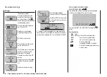
Carefully raise the central lug of the connector slight-
ly (1), withdraw the red
wire (2) and insulate the
bare contact with tape
to avoid possible short
circuits (3).
red
1
2
3
Reset
To carry out a receiver reset, locate the
SET
button on
the top of the receiver and hold it pressed in while you
switch the receiver power supply on. Hold the receiver’s
SET
button pressed in until the green and the red LED
goes out; this takes about four seconds.
If you carried out the reset with the transmitter switched
off, or with an unbound receiver, the receiver LED will
flash red slowly after a pause lasing about two seconds.
At this point it is immediately possible to initiate a Bind
process at the transmitter.
If the reset is carried out with an already bound receiver,
if the transmitter is switched on, and if the associated
model memory is active, then the LED lights up green
after a short interval to indicate that your transmitter /
receiving system is ready for use once more.
* Battery Elimination Circuit
Содержание mx-12 Hott
Страница 1: ...Programming Manual 33116 mx 16 HoTT 3 en mx 16...
Страница 35: ...35 For your notes...
Страница 49: ...49 For your notes...
Страница 55: ...55 For your notes...
Страница 59: ...59 For your notes...
Страница 63: ...63 For your notes...
Страница 69: ...69 For your notes...
Страница 91: ...91 For your notes...
Страница 101: ...101 For your notes...
Страница 123: ...123 For your notes...
Страница 181: ...181 For your notes...
Страница 193: ...193 For your notes...

