FC9000-UM-251-9370 8-8
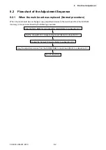
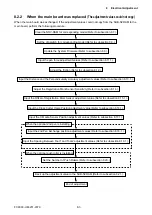
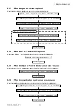
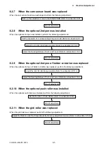
8 Electrical Adjustment
8.4 Explanation of the Values of the Main Board Settings
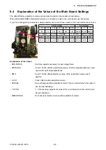
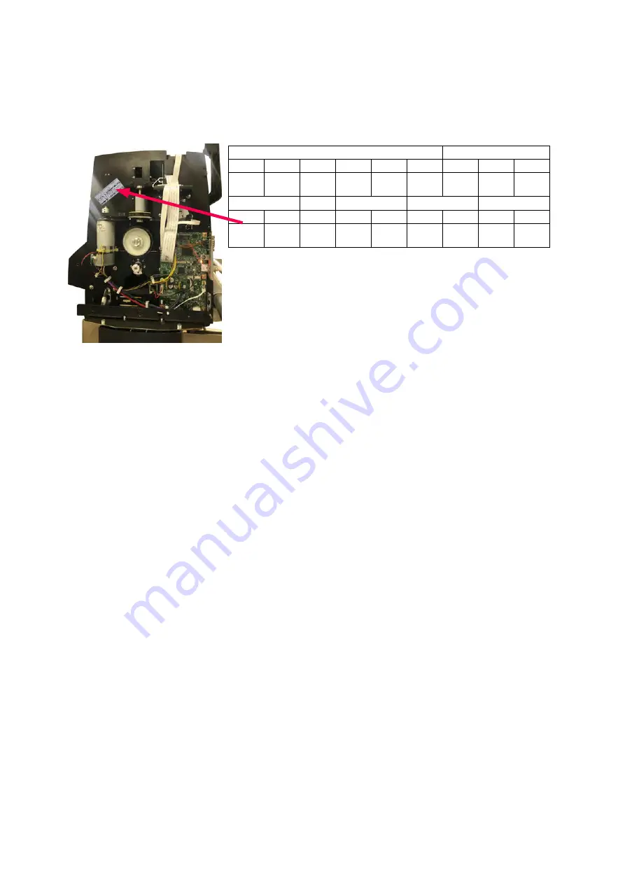
The default factory adjustment values are recorded on label in the location shown below.
When the SUB-NVRAM of adjustment values are not able to copy to the main board, use this values.
If you have changed any values by making adjustments, record those values for the next maintenance check.
PEN FORCE
DISTANCE
10
48
130
210
515
618
X
Y
Z
xx
xx
xxx
xxx
xxx
xxx xxx.xx xxx.xx xxx.xx
RMS
C-CUT
PENSEL
1-2TOOL
MEDIA SENS
X
Y
Y
Y
H
X
Y
F
R
xx.xx xx.xx xx.xx xx.xx xx.xx xx.xx xx.xx xx.xx xx.xx
Explanation of the values
• PEN FORCE
Pen force adjustment values for each target force.
• DISTANCE
X and Y for the distance adjustment value, Z for the diagonal distance value
used to the right angle adjustment.
• RMS
X and Y for the offset adjustment value of the registration mark sensor
position.
• C-CUT
Cross cutter position adjustment value.
• PENSEL
Pen exchange position adjustment value (This is recorded when the option 2
pen kit was installing.).
• 1-2TOOL
1 - 2 Tool spacing adjustment value (This is recorded when the option 2 pen
kit was installing.).
• MEDIA SENS
Front and rear media sensor position adjustment values.
Содержание FC9000-100
Страница 1: ...CUTTING PLOTTER SERVICE MANUAL FC9000 75 100 140 160 FC9000 UM 251 01 9370...
Страница 2: ......
Страница 4: ...FC9000 UM 251 9370 II...
Страница 38: ......
Страница 201: ...FC9000 UM 251 9370 10 2 10 PARTS LIST Outer Casing 1 2 3 4 10 7 11 5 16 15 6 12 12 9 13 14 8...
Страница 211: ...FC9000 UM 251 9370 10 12 10 PARTS LIST Stand Basket 3 4 6 9 8 7 10 13 11 9 14 12 6 5 1 1 2 2 15...
Страница 216: ...FC9000 UM 251 9370 10 17 10 PARTS LIST...


