
FC9000-UM-251-9370 7-23
7 DISASSEMBLY AND REASSEMBLY
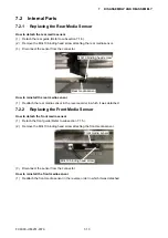
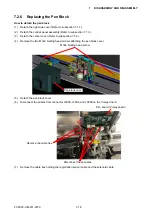
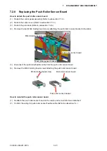
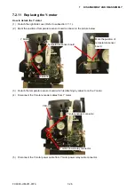
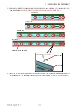
7.2.8 Replacing the Push Roller Sensor Board
How to detach the push roller sensor board
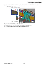
(1) Detach the control panel assembly (Refer to subsection 7.1.3.).
(2) Detach the center cover (Refer to subsection 7.1.4.).
(3) Detach the pen block (Refer to subsection 7.2.6.).
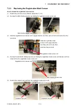
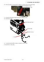
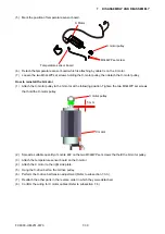
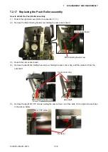
(4) Remove the two M3L6 binding head screws attaching the push roller sensor bracket to the slider.
Y slider
M3L6 binding head screw
Push roller sensor bracket
Push roller sensor board
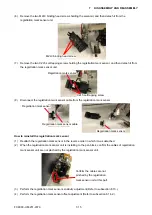
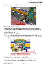
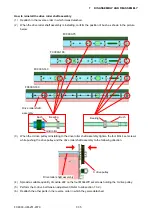
(5)
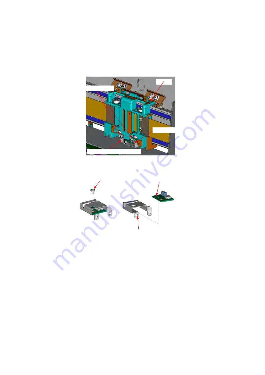
Disconnect the push roller flexible cable from the push roller sensor board.
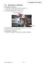
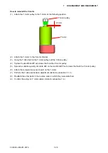
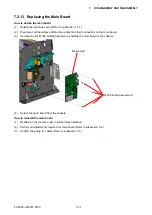
(6) Remove the M3L4 binding head screws attaching the push roller sensor board.
Push roller sensor board
Push roller sensor bracket
M3L4 binding head screw
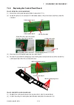
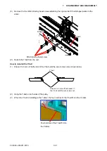
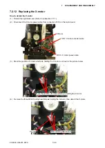
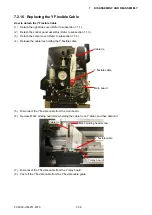
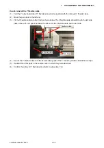
How to reinstall the push roller sensor board
(1) Reattach the push roller sensor board in the reverse order in which it was detached.
(2)
Confirm the wiring for push roller sensor flexible cable (Refer to subsection 7.4.).
Содержание FC9000-100
Страница 1: ...CUTTING PLOTTER SERVICE MANUAL FC9000 75 100 140 160 FC9000 UM 251 01 9370...
Страница 2: ......
Страница 4: ...FC9000 UM 251 9370 II...
Страница 38: ......
Страница 201: ...FC9000 UM 251 9370 10 2 10 PARTS LIST Outer Casing 1 2 3 4 10 7 11 5 16 15 6 12 12 9 13 14 8...
Страница 211: ...FC9000 UM 251 9370 10 12 10 PARTS LIST Stand Basket 3 4 6 9 8 7 10 13 11 9 14 12 6 5 1 1 2 2 15...
Страница 216: ...FC9000 UM 251 9370 10 17 10 PARTS LIST...


