FC9000-UM-251-9370 7-45
7 DISASSEMBLY AND REASSEMBLY
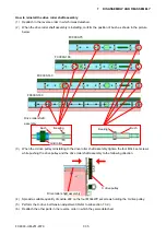
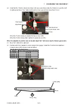
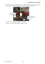
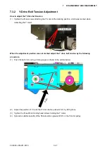
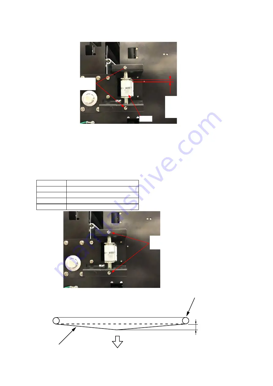
(2) Verify that the Y belt is centered and does not move up and down when the Y-slider is moved from left
to right several times. The Y-slider belt should not move up and down more than 1.5 mm.
The Y belt should not
move up and down more
than 1.5 mm.
Y belt
Y belt tension
adjustment screws
When the Y belt is moving up, tighten the lower screw a little.
When the Y belt is moving down, tighten the upper screw a little.
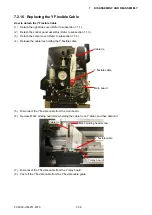
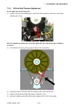
When the adjustment position was not marked adjust the Y belt tension by the following procedure.
(1) Move the Y-slider to the right end.
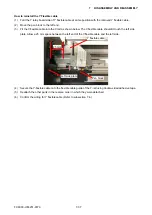
(2) Pull the belt 20 mm towards the center using a force gauge. Adjust the Y belt tension adjustment
screws evenly until the tension reads as follows:
Specification of the Belt Tension
Model
Force gauge reading specification
FC9000-75
700 g+50
FC9000-100
700 g+50
FC9000-140
700 g+50
FC9000-160
700 g+50
Adjustment screw
(M3L28 binding head screw)
20 mm
700 g + 50g
Y idler pulley
Y belt
Содержание FC9000-100
Страница 1: ...CUTTING PLOTTER SERVICE MANUAL FC9000 75 100 140 160 FC9000 UM 251 01 9370...
Страница 2: ......
Страница 4: ...FC9000 UM 251 9370 II...
Страница 38: ......
Страница 201: ...FC9000 UM 251 9370 10 2 10 PARTS LIST Outer Casing 1 2 3 4 10 7 11 5 16 15 6 12 12 9 13 14 8...
Страница 211: ...FC9000 UM 251 9370 10 12 10 PARTS LIST Stand Basket 3 4 6 9 8 7 10 13 11 9 14 12 6 5 1 1 2 2 15...
Страница 216: ...FC9000 UM 251 9370 10 17 10 PARTS LIST...

