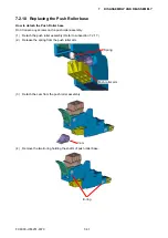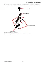
FC9000-UM-251-9370 7-27
7 DISASSEMBLY AND REASSEMBLY
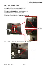
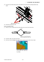
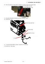
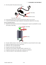
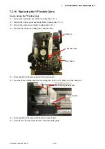
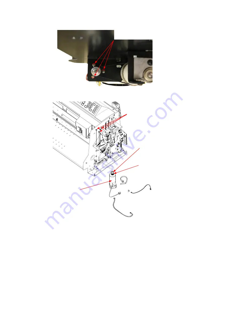
(6) Mark the position of screws which are holding the Y motor as shown in the picture below.
Mark the position of screws
which are holding the Y motor.
(7) Remove the three M3L6 binding head screws holding the Y-motor.
(8) Detach the Y-motor.
2
3
2
3
4
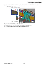
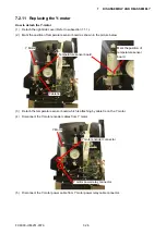
Y motor
M3L6 binding head screw
M3L4WP set screw
Y motor pulley
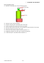
(9) Loosen the two M3L4WP set screws to detach the Y-motor pulley.
(10) Detach the Y-motor pulley.
Содержание FC9000-100
Страница 1: ...CUTTING PLOTTER SERVICE MANUAL FC9000 75 100 140 160 FC9000 UM 251 01 9370...
Страница 2: ......
Страница 4: ...FC9000 UM 251 9370 II...
Страница 38: ......
Страница 201: ...FC9000 UM 251 9370 10 2 10 PARTS LIST Outer Casing 1 2 3 4 10 7 11 5 16 15 6 12 12 9 13 14 8...
Страница 211: ...FC9000 UM 251 9370 10 12 10 PARTS LIST Stand Basket 3 4 6 9 8 7 10 13 11 9 14 12 6 5 1 1 2 2 15...
Страница 216: ...FC9000 UM 251 9370 10 17 10 PARTS LIST...

