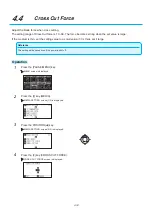
4-3
Supplement
•
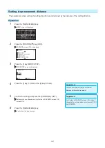
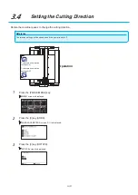
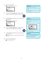
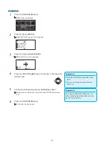
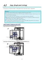
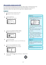
Coordinate value displayed here is the
distance to the tool carriage from the origin
point.
•
Press [1] key (DEFAULT) if the cutting are is
not to change.
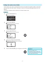
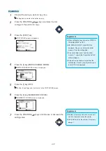
3
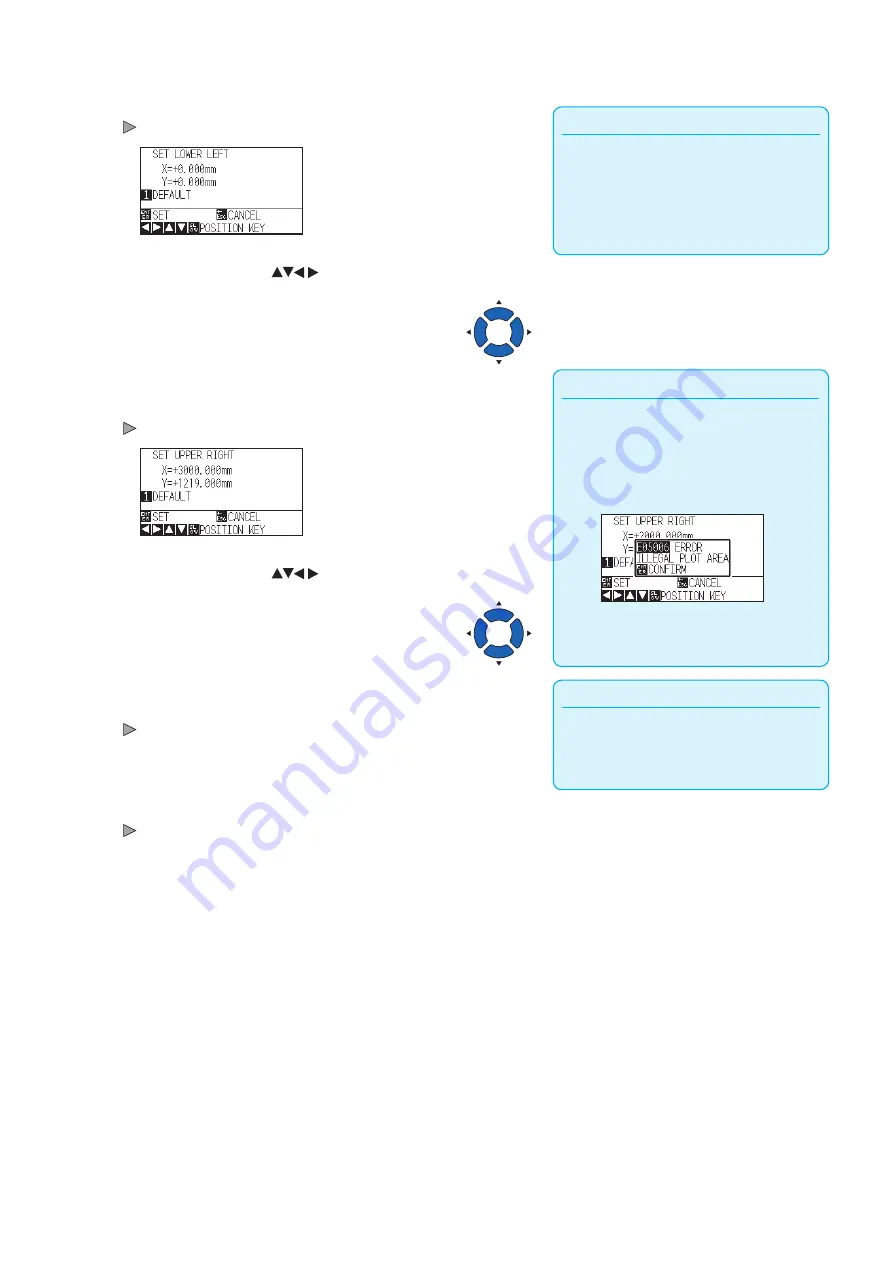
Press the [1] key (AREA).
SET LOWER LEFT screen is displayed.
4
Press the POSITION (
) keys and move the tool
carriage to the position to be the lower left of the AREA.
5
Press the [ENTER] key (SET) once the tool carriage is in
correct position.
SET UPPER RIGHT screen is displayed.
Supplement
Please set the X and Y cut range for the areas
on the upper right and lower left points to at
least 10 mm.
An error message will appear for areas that are
too small.
You will need to reset the settings for the upper
right and lower left points.
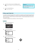
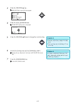
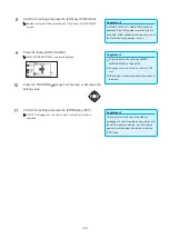
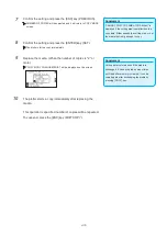
6
Press the POSITION (
) keys and move the tool
carriage to the upper right position of the AREA.
Supplement
It will return to AREA PARAMETERS screen
(1/1) without changing the settings when you
press the [ESC] key (CANCEL).
7
Press the [ENTER] key (SET) once the tool carriage is in
correct position.
Setting will be confirmed and it will return to AREA PARAMETERS
screen (1/1).
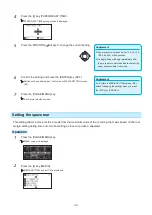
8
Press the [PAUSE/MENU] key.
It will return to default screen.
Содержание CE7000-130AP
Страница 1: ...USER S MANUAL MANUAL NO CE70AP UM 151 CE7000 130AP CUTTING PLOTTER...
Страница 2: ......
Страница 19: ...1 3 Dedicated accessories A stand with a basket is supplied...
Страница 84: ......
Страница 104: ......
Страница 110: ......
Страница 128: ......
Страница 184: ......
Страница 245: ...A 7 PAUSE MENU 2 Continued MENU screen AXIS SETTING 1 1 Default screen Continued 1 2...
Страница 246: ...A 8 3 PAUSE MENU Continued MENU screen AREA PARAMETERS 1 1 Default screen Continued 1 2 3 4...
Страница 250: ...A 12 PAUSE MENU Continued MENU screen TEST 1 2 TEST 2 2 Default screen Continued 2 3 1 1 4...
Страница 251: ...A 13 PAUSE MENU MENU screen MEM SETTING 1 1 1 Default screen Continued Default screen Finish...
Страница 254: ......
Страница 258: ......
Страница 260: ......

