Repair Manual MSG 90.6PG Commercial Vehicles, Omnibuses – November 2017
Material no. 1153450_c
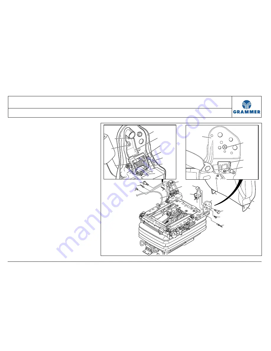
3.32 Bearing support with backrest locking mechanism and hook-in
function – removal and installation
Page 3 of 14
REMOVAL INSTALLATION
TABLE OF CONTENTS
Note:
If screws are included in the scope of
delivery of spare parts which are not
micro-encapsulated, an appropriate
threadlocking compound (e.g. LOCTITE)
has to be used.
1 Lift off the seat cushion in position for
repair (Chapter 3.1).
2 Seat with operator console and
armrest for electro-pneumatic
gearshift:
Remove the operator console for the
electro-pneumatic gearshift (see
Chapter 3.25).
3 Remove the left covering in position
for repair (Chapter 3.4).
5
11
6
10
19
19
9
12
2
18
8
3
1
4
5
14
2
12
11
9
6
5
4
5
7
7
5
15
16
17
1
3
14
13
2233


