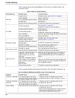
20
Operation
4.
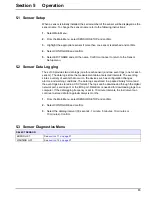
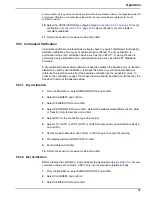
Select PERFORM TEST and confirm. Select the available Output Mode (Active, Hold,
or Transfer) from the list box and confirm.
5.
Select WET for the verification type and confirm.
6.
Enter the Std Turbidity and confirm.
7.
Drain and clean the sensor body and confirm.
8.
Pour the standard into cylinder. Replace the head and confirm.
9.
The reading will be displayed. Confirm to accept the verification.
10. Return the sensor to measure mode and confirm.
5.6 Calibration and Verification History
The calibration and verification history logs contain information on the last 12 calibrations
and the last 12 verifications. The calibration history log shows the gain value, the time and
date of the calibration, and the initials of the operator performing verification.
Note: Restoring default settings from the DIAG/TEST menu will return the turbidimeter to its non
calibration state (gain = 1.0) but it will not remove the previous calibration history from memory.
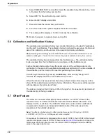
The calibration history log is accessed from the Calibrate menu. The verification history
log is accessed from the Verification menu (a submenu of the Calibrate menu).
Each verification history entry shows the serial number of the verification device (dry
verification) or the value of the verification standard (wet verification), the time and date of
the verification, and the initials of the operator performing the verification.
Scroll through the entries by pressing the
ENTER
key. After scrolling through all 12
histories, the display will return to the calibration menu level.
When the instrument is received from the factory, default values or blank spaces will be
shown for the calibration and verification history information. Those values will be replaced
with real data as the history log is filled.
The data is retained as first in, first out. When the log is full, the newest entry is stored and
the oldest entry in the log is deleted.
5.7 Offset Feature
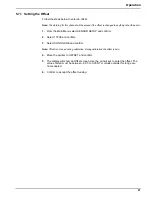
The offset or clean water offset (CWO) feature will allow a ± 0.05 NTU offset to the
measured value. The offset value denoted as CWO will be subtracted from the value
displayed on the sc Interface. The 0.05 NTU offset can be entered after a calibration is
complete and is based on an independent determination of the water used in the
preparation of the turbidity standards.
Note: The offset is a limited value. An offset outside the range of ± 0.05 mg/L, ± 0.05 NTU,
± 0.05 TE/F, ± 0.05 FTU or ± 0.05 Degree will not be accepted.
For example, if a standard is prepared with a value of 0.8 NTU, the 0.05 NTU offset would
result in a displayed value of 0.75 NTU. See the
Setting the Offset
section to change the
offset value. When the offset is used, the letters CWO are displayed after the turbidity
value in the upper-right corner.
Содержание VG3B3-B
Страница 14: ...GENERAL INFORMATION...
Страница 17: ...EQUIPMENT SAFETY DOCUMENTS and PRECAUTIONS...
Страница 30: ...U L MOTOR REQUIREMENTS...
Страница 31: ......
Страница 35: ...PROTECTIVE COATINGS...
Страница 37: ...PAINT TECHNICAL DATA SHEETS...
Страница 43: ...PASSIVATION DOCUMENTS...
Страница 47: ...STORAGE PROCEDURES...
Страница 51: ...INSTRUMENTATION...
Страница 56: ...VALVES...
Страница 58: ...PUMPS...
Страница 61: ...MATERIAL SAFETY DATA SHEETS...
Страница 65: ......
Страница 66: ...PAINT COATING MSDS...
Страница 73: ...ADHESIVE ANCHORS MSDS...
Страница 74: ...SIMPSON...
Страница 95: ......
Страница 96: ......
Страница 97: ......
Страница 98: ......
Страница 99: ......
Страница 100: ...INSTALLATION AND START UP...
Страница 103: ...START UP PAPERS...
Страница 125: ...PROCESS AND CONTROL...
Страница 181: ...MECHANICAL AND FIELD INSTRUMENT COMPONENT INFORMATION...
Страница 182: ...ACTUATOR...
Страница 183: ...CORD SET...
Страница 185: ...AUMA...
Страница 186: ...115V 1ph 60Hz...
Страница 190: ...ANCHORS...
Страница 191: ...ADHESIVE ANCHOR See Drawing Section 7 for Details...
Страница 192: ...MANUAL GUN...
Страница 194: ...REFILL PACK...
Страница 197: ...MIXING NOZZLE...
Страница 199: ...INSTRUMENTATION...
Страница 200: ...CONTROLLER...
Страница 201: ...THERMO FISHER...
Страница 203: ...pH PROBE...
Страница 205: ...pH Probe Assembly Part 2966753 Sensor Head Data Stick Adapter 2012 11 28 2966753 pH Probe Assembly doc 2 of 2...
Страница 206: ...FLOW METER...
Страница 211: ...PRESSURE TRANSMITTER...
Страница 213: ...PUMP...
Страница 214: ...MEMBRANE FEED PUMP...
Страница 217: ...Pump Part 2616713 Gorman Rupp VG3B3 B Centrifugal 2013 12 09 2616713 Pump doc 3 of 3...
Страница 220: ...BACKWASH PUMP...
Страница 223: ...Pump Part 2616695 Gorman Rupp VG3C3 B Centrifugal 2013 12 09 2616695 Pump doc 3 of 3...
Страница 227: ...BUTTERFLY VALVE...
Страница 228: ...MANUAL LEVER BUTTERFLY VALVE...
Страница 238: ...ELECTRIC BUTTERFLY VALVE...
Страница 241: ...SWING CHECK VALVE...
Страница 243: ...SOLENOID VALVE...
Страница 245: ...MEMBRANE MODULE ACCESSORIES...
Страница 254: ...AIR COMPRESSOR ACCESSORIES...
Страница 258: ...ELECTRICAL CONTROL PANEL COMPONENT INFORMATION...
Страница 265: ...CABLE CONDUIT WIRE...
Страница 271: ...CIRCUIT BREAKER...
Страница 281: ...COMPUTER and MONITOR...
Страница 289: ...ENCLOSURE...
Страница 291: ...Type 12 Enclosure Part 2750002 Hoffman Two Door Floor Mount 2011 03 03 2750002 Hoffman Type 12 Enclosure doc 2 of 2...
Страница 293: ...Type 12 Enclosure Part 2750149 Hoffman Two Door Floor Mount 2007 07 09 2750149 Hoffman Type 12 Enclosure doc 2 of 2...
Страница 295: ...4X Fiberglass Enclosure Part 2750251 Hoffman ULTRX 2007 07 09 2750251 Hoffman 4X Fiberglass Enclosure doc 2 of 2...
Страница 296: ...ENCLOSURE ACCESSORIES...
Страница 307: ...ENVIRONMENTAL CONTROL ENCLOSURE...
Страница 310: ...Heat Exchanger Part 2752664 Hoffman XR472416012 2013 11 08 2752664 Heat Exchanger doc 2 of 3 Dimensions...
Страница 311: ...Heat Exchanger Part 2752664 Hoffman XR472416012 2013 11 08 2752664 Heat Exchanger doc 3 of 3 Cutout Dimensions...
Страница 313: ...Temperature Control Switch Part 2700943 Hoffman ATEMNO 2014 04 30 2700943 Hoffman Temperature Switch doc 2 of 2...
Страница 314: ...FUSE...
Страница 329: ...FUSE BLOCK...
Страница 336: ...HMI HUMAN MACHINE INTERFACE...
Страница 343: ...MAIN DISCONNECT...
Страница 350: ...MAIN DISCONNECT ACCESSORIES...
Страница 354: ...MOTOR CONTROL...
Страница 368: ...NETWORK...
Страница 374: ...Ethernet Switch Part 2702571 N TRON 708FX2 SC 2013 12 16 2702571 Ethernet Switch doc 3 of 3 Dimensions...
Страница 379: ...PILOT DEVICE...
Страница 392: ...PLC PROGRAMMABLE LOGIC CONTROL...
Страница 394: ...Analog Input Module Part 2701835 Allen Bradley CompactLogix 2008 01 30 2701835 AB Analog Input CompactLogix doc 2 of 3...
Страница 395: ...Analog Input Module Part 2701835 Allen Bradley CompactLogix 2008 01 30 2701835 AB Analog Input CompactLogix doc 3 of 3...
Страница 406: ...Power Supply Part 2701833 Allen Bradley CompactLogix 2008 01 11 2701833 AB Power Supply CompactLogix doc 2 of 2...
Страница 416: ...Flex I O Ethernet Adapter Part 2702281 Allen Bradley 2008 01 30 2702281 AB Flex IO Ethernet Module doc 2 of 4...
Страница 417: ...Flex I O Ethernet Adapter Part 2702281 Allen Bradley 2008 01 30 2702281 AB Flex IO Ethernet Module doc 3 of 4...
Страница 418: ...Flex I O Ethernet Adapter Part 2702281 Allen Bradley 2008 01 30 2702281 AB Flex IO Ethernet Module doc 4 of 4...
Страница 420: ...PRINTERS...
Страница 424: ...POWER SUPPLY...
Страница 426: ...Power Supply Part 2751312 Allen Bradley 2008 02 28 2751312 AB Power Supply doc 2 of 5...
Страница 427: ...Power Supply Part 2751312 Allen Bradley 2008 02 28 2751312 AB Power Supply doc 3 of 5...
Страница 428: ...Power Supply Part 2751312 Allen Bradley 2008 02 28 2751312 AB Power Supply doc 4 of 5...
Страница 429: ...Power Supply Part 2751312 Allen Bradley 2008 02 28 2751312 AB Power Supply doc 5 of 5...
Страница 431: ...Power Supply Part 2750761 DS 2750761 AB Power Supply doc 2 of 4 Copyright 2007 Aqua Aerobic Systems Inc 2013 01 14...
Страница 432: ...Power Supply Part 2750761 DS 2750761 AB Power Supply doc 3 of 4 Copyright 2007 Aqua Aerobic Systems Inc 2013 01 14...
Страница 433: ...Power Supply Part 2750761 DS 2750761 AB Power Supply doc 4 of 4 Copyright 2007 Aqua Aerobic Systems Inc 2013 01 14...
Страница 434: ...RELAY CONTROL...
Страница 436: ...Relay Part 2752020 Allen Bradley 700 HA32A1 4 2013 06 28 2752020 AB 700 HA34A1 4 Relay doc 2 of 3 Specifications...
Страница 440: ...SURGE SUPPRESSOR TRANSIENT FILTER...
Страница 442: ...Active Tracking Filter Part 2700906 Islatrol IC 105 2014 04 28 2700906 Islatrol Active Tracking Filter doc 2 of 2...
Страница 447: ...TERMINAL BLOCK ACCESSORIES...
Страница 471: ...TIMERS...
Страница 475: ...Relay Socket Part 2702163 ATC 2008 12 12 2702163 Delayed Interval Relay Socket doc 2 of 2 Wiring Diagram...
Страница 477: ...TRANSFORMER ACCESSORIES...
Страница 482: ...UPS UNINTERRUPTIBLE POWER SUPPLY...
Страница 489: ...MAINTENANCE AND TROUBLESHOOTING...
Страница 498: ...COMPONENT PRODUCTS EQUIPMENT O M INSTRUCTION MANUALS...
Страница 499: ...ACTUATOR...
Страница 500: ...ELECTRIC...
Страница 501: ...Electric part turn actuators Operation instructions SG 05 1 SG 12 1 SGR 05 1 SGR 12 1 AUMA NORM for flange type FA...
Страница 534: ...ADHESIVE ANCHOR O M...
Страница 535: ......
Страница 537: ...INSTRUMENTATION O M...
Страница 538: ...FLOW METER...
Страница 684: ...5 NOTES 30 IFC 100 www krohne com 07 2010 4000124104 QS IFC 100 R04 en...
Страница 685: ...NOTES 5 31 IFC 100 www krohne com 07 2010 4000124104 QS IFC 100 R04 en...
Страница 687: ......
Страница 688: ......
Страница 689: ......
Страница 690: ......
Страница 691: ......
Страница 692: ......
Страница 693: ......
Страница 694: ......
Страница 695: ......
Страница 696: ......
Страница 697: ......
Страница 698: ......
Страница 699: ......
Страница 700: ......
Страница 701: ......
Страница 702: ......
Страница 703: ......
Страница 704: ......
Страница 705: ......
Страница 706: ......
Страница 707: ......
Страница 708: ......
Страница 709: ......
Страница 710: ......
Страница 711: ......
Страница 712: ......
Страница 713: ......
Страница 714: ......
Страница 715: ......
Страница 716: ......
Страница 717: ......
Страница 718: ......
Страница 719: ......
Страница 720: ......
Страница 721: ......
Страница 722: ......
Страница 723: ...TURBIDITY MONITORING O M...
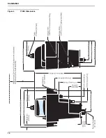
Страница 734: ...10 Installation Figure 4 1720E Dimensions...
Страница 738: ...14 System Startup...
Страница 746: ...22 Operation...
Страница 754: ...30 Troubleshooting...
Страница 760: ...36 Modbus Register Information...
Страница 762: ...38 Index...
Страница 763: ...DOC023 53 80221 FT660 sc 01 2012 Edition 2 User Manual...
Страница 764: ......
Страница 782: ...1 2 18 English...
Страница 783: ...3 4 English 19...
Страница 790: ...26 English...
Страница 791: ......
Страница 793: ...CONTROLLER...
Страница 794: ...Thermo Scientific AquaSensors AV38 Local Display and Controller User Guide...
Страница 873: ......
Страница 875: ...pH PROBE...
Страница 880: ...PRESSURE TRANSMITTER...
Страница 881: ......
Страница 900: ...A 9 Keller America Inc User s Guide Rev 10 11...
Страница 901: ...A 10 Keller America Inc User s Guide Rev 10 11...
Страница 904: ...MEMBRANE MODULE...
Страница 905: ...inge GmbH Installation Operation and Maintenance Guidelines inge T Rack vario...
Страница 934: ......
Страница 935: ...Appendix B Process Specification inge UF...
Страница 957: ...PUMPS...
Страница 958: ...GORMAN RUPP PUMP...
Страница 959: ......
Страница 960: ......
Страница 961: ......
Страница 962: ......
Страница 963: ......
Страница 964: ......
Страница 965: ......
Страница 966: ......
Страница 967: ......
Страница 968: ......
Страница 969: ......
Страница 970: ......
Страница 971: ......
Страница 972: ......
Страница 973: ......
Страница 974: ......
Страница 975: ......
Страница 976: ......
Страница 977: ......
Страница 978: ......
Страница 979: ......
Страница 980: ......
Страница 981: ......
Страница 982: ......
Страница 983: ......
Страница 984: ......
Страница 985: ......
Страница 986: ......
Страница 987: ......
Страница 988: ......
Страница 989: ......
Страница 990: ......
Страница 991: ......
Страница 1013: ...OM 02812 VG SERIES MAINTENANCE REPAIR PAGE E 2 SECTION DRAWING PARTSPAGE Figure 1 Pump Model VG3C3 B...
Страница 1056: ...VALVES...
Страница 1057: ...NIBCO VALVE...
Страница 1058: ...WAFER BUTTERFLY VALVE...
Страница 1068: ...MILLIKEN VALVE...
Страница 1069: ...MILLIKEN BUTTERFLY VALVE...
Страница 1070: ......
Страница 1075: ...5 OPERATION MAINTENANCE ILLUSTRATION 3 Q DIMENSION 3 4 6 8 10 12 14 16 18 20 24 2 75 4 88 5 57 8 38 10 5 13 13 15 25 17 38 21 38...
Страница 1077: ...MECHANICAL DRAWINGS...
Страница 1110: ...ELECTRICAL DRAWINGS...
Страница 1119: ......
Страница 1153: ......
Страница 1157: ......

