12
C-SAS-2009 ©
2009 SIMPSON STRONG-TIE COMP
ANY INC.
Simpson Strong-Tie Company Inc. structural connectors, anchors and other
products are designed and tested to provide specifi ed design loads. To obtain
optimal performance from Simpson Strong-Tie Company Inc. products and
achieve maximum allowable design load and design strength, the products
must be properly installed and used in accordance with the installation
instructions and design limits provided by Simpson Strong-Tie Company Inc.
To ensure proper installation and use, designers and installers must carefully
read the following General Notes, General Instructions for the Installer and
General Instructions for the Designer as well as consult the applicable catalog
pages for specifi c product installation instructions and notes. If you do not
understand the catalog, or if you have any questions, contact Simpson
Strong-Tie Company Inc. for further information.
In addition to following all notes, warnings and instructions provided in the
catalog, installers, designers, engineers and consumers should consult the
Simpson Strong-Tie Company Inc. web site at
www.simpsonanchors.com
to
obtain additional design and installation information.
Failure to follow fully all of the notes and instructions provided by Simpson
Strong-Tie Company Inc. may result in improper design or installation of
products. Improperly designed or installed products may not perform to the
specifi cations set forth in this catalog and may reduce a structure’s ability to
resist the movement, stress and loading that occurs from gravity loads as well
as impact events such as earthquakes and high velocity winds.
Simpson Strong-Tie Company Inc. does not guarantee the performance
or safety of products that are modifi ed, improperly installed, or not used in
accordance with the design and load limits set forth in this catalog.
These general notes are provided to ensure proper installation of
Simpson Strong-Tie Company Inc products and must be followed fully.
a) Simpson Strong-Tie Company Inc. reserves the
right to change specifi cations, designs, and models
without notice or liability for such changes.
b) Unless otherwise noted, dimensions are in
inches and loads are in pounds.
c) Do not overload, which will jeopardize the anchorage. Service loads shall
not exceed published allowable loads. Factored loads shall not exceed
design strengths calculated in accordance with published design data.
d) Some hardened fasteners may experience premature failure if exposed
to moisture. These fasteners are recommended to be used in dry
interior applications.
e) Do not weld products listed in this catalog. Some steel types
have poor weldability and a tendency to crack when welded.
WARNING
GENERAL NOTES
GENERAL INSTRUCTIONS FOR THE INSTALLER
These general instructions for the installer are provided to ensure the
proper selection and installation of Simpson Strong-Tie Company Inc.
products and must be followed carefully. These general instructions are in
addition to the specifi c design and installation instructions and notes provided
for each particular product, all of which should be consulted prior to and
during the installation of Simpson Strong-Tie Company Inc. products.
a) Do not modify Simpson Strong-Tie Company Inc. products. The
performance of modifi ed products may be substantially weakened.
Simpson Strong-Tie will not warrant or guarantee the performance of
such modifi ed products.
b) Do not alter installation procedures from those set forth in this catalog.
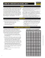
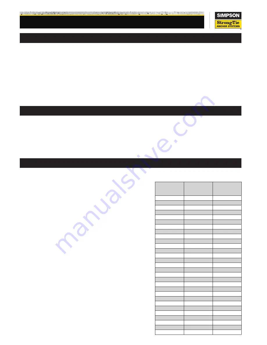
c) Drill holes for mechanical anchors with carbide-tipped drill bits meeting
the diameter requirements of ANSI B212.15 shown in the table below.
A properly-sized hole is critical to the performance of mechanical
anchors. Rotary-hammer drills with light, high-frequency impact are
recommended for drilling holes. When holes are to be drilled in archaic
or hollow base materials, the drill should be set to “rotation-only” mode.
d) For mechanical anchors that require a specifi c installation torque: Failure
to apply the recommended installation torque can result in excessive
displacement of the anchor under load or premature failure of the
anchor. These anchors will lose pre-tension after setting due to pre-load
relaxation. See Supplemental Topic M1 on page 14 for more information.
e) Do not disturb, bolt up, or apply load to adhesive anchors prior to the
full cure of the adhesive.
f) For powder-actuated fastening, refer to the Important Information
on page 183.
g) Use proper safety equipment.
Nominal Drill Bit
Diameter
(in.)
Tolerance Range
Minimum
(in.)
Tolerance Range
Maximum
(in.)
¹⁄₈
0.134
0.140
⁵⁄₃₂
0.165
0.171
³⁄₁₆
0.198
0.206
⁷⁄₃₂
0.229
0.237
¹⁄₄
0.260
0.268
⁵⁄₁₆
0.327
0.335
³⁄₈
0.390
0.398
⁷⁄₁₆
0.458
0.468
¹⁄₂
0.520
0.530
⁹⁄₁₆
0.582
0.592
⁵⁄₈
0.650
0.660
¹¹⁄₁₆
0.713
0.723
³⁄₄
0.775
0.787
¹³⁄₁₆
0.837
0.849
²⁷⁄₃₂
0.869
0.881
⁷⁄₈
0.905
0.917
¹⁵⁄₁₆
0.968
0.980
1
1.030
1.042
1¹⁄₈
1.160
1.175
1³⁄₁₆
1.223
1.238
1¹⁄₄
1.285
1.300
1⁵⁄₁₆
1.352
1.367
1³⁄₈
1.410
1.425
1⁷⁄₁₆
1.472
1.487
1¹⁄₂
1.535
1.550
1⁹⁄₁₆
1.588
1.608
1⁵⁄₈
1.655
1.675
1³⁄₄
1.772
1.792
2
2.008
2.028
Finished Diameters for Rotary and Rotary Hammer
Carbide Tipped Concrete Drills per ANSI B212.15
IMPORTANT INFORMATION AND GENERAL NOTES
Содержание VG3B3-B
Страница 14: ...GENERAL INFORMATION...
Страница 17: ...EQUIPMENT SAFETY DOCUMENTS and PRECAUTIONS...
Страница 30: ...U L MOTOR REQUIREMENTS...
Страница 31: ......
Страница 35: ...PROTECTIVE COATINGS...
Страница 37: ...PAINT TECHNICAL DATA SHEETS...
Страница 43: ...PASSIVATION DOCUMENTS...
Страница 47: ...STORAGE PROCEDURES...
Страница 51: ...INSTRUMENTATION...
Страница 56: ...VALVES...
Страница 58: ...PUMPS...
Страница 61: ...MATERIAL SAFETY DATA SHEETS...
Страница 65: ......
Страница 66: ...PAINT COATING MSDS...
Страница 73: ...ADHESIVE ANCHORS MSDS...
Страница 74: ...SIMPSON...
Страница 95: ......
Страница 96: ......
Страница 97: ......
Страница 98: ......
Страница 99: ......
Страница 100: ...INSTALLATION AND START UP...
Страница 103: ...START UP PAPERS...
Страница 125: ...PROCESS AND CONTROL...
Страница 181: ...MECHANICAL AND FIELD INSTRUMENT COMPONENT INFORMATION...
Страница 182: ...ACTUATOR...
Страница 183: ...CORD SET...
Страница 185: ...AUMA...
Страница 186: ...115V 1ph 60Hz...
Страница 190: ...ANCHORS...
Страница 191: ...ADHESIVE ANCHOR See Drawing Section 7 for Details...
Страница 192: ...MANUAL GUN...
Страница 194: ...REFILL PACK...
Страница 197: ...MIXING NOZZLE...
Страница 199: ...INSTRUMENTATION...
Страница 200: ...CONTROLLER...
Страница 201: ...THERMO FISHER...
Страница 203: ...pH PROBE...
Страница 205: ...pH Probe Assembly Part 2966753 Sensor Head Data Stick Adapter 2012 11 28 2966753 pH Probe Assembly doc 2 of 2...
Страница 206: ...FLOW METER...
Страница 211: ...PRESSURE TRANSMITTER...
Страница 213: ...PUMP...
Страница 214: ...MEMBRANE FEED PUMP...
Страница 217: ...Pump Part 2616713 Gorman Rupp VG3B3 B Centrifugal 2013 12 09 2616713 Pump doc 3 of 3...
Страница 220: ...BACKWASH PUMP...
Страница 223: ...Pump Part 2616695 Gorman Rupp VG3C3 B Centrifugal 2013 12 09 2616695 Pump doc 3 of 3...
Страница 227: ...BUTTERFLY VALVE...
Страница 228: ...MANUAL LEVER BUTTERFLY VALVE...
Страница 238: ...ELECTRIC BUTTERFLY VALVE...
Страница 241: ...SWING CHECK VALVE...
Страница 243: ...SOLENOID VALVE...
Страница 245: ...MEMBRANE MODULE ACCESSORIES...
Страница 254: ...AIR COMPRESSOR ACCESSORIES...
Страница 258: ...ELECTRICAL CONTROL PANEL COMPONENT INFORMATION...
Страница 265: ...CABLE CONDUIT WIRE...
Страница 271: ...CIRCUIT BREAKER...
Страница 281: ...COMPUTER and MONITOR...
Страница 289: ...ENCLOSURE...
Страница 291: ...Type 12 Enclosure Part 2750002 Hoffman Two Door Floor Mount 2011 03 03 2750002 Hoffman Type 12 Enclosure doc 2 of 2...
Страница 293: ...Type 12 Enclosure Part 2750149 Hoffman Two Door Floor Mount 2007 07 09 2750149 Hoffman Type 12 Enclosure doc 2 of 2...
Страница 295: ...4X Fiberglass Enclosure Part 2750251 Hoffman ULTRX 2007 07 09 2750251 Hoffman 4X Fiberglass Enclosure doc 2 of 2...
Страница 296: ...ENCLOSURE ACCESSORIES...
Страница 307: ...ENVIRONMENTAL CONTROL ENCLOSURE...
Страница 310: ...Heat Exchanger Part 2752664 Hoffman XR472416012 2013 11 08 2752664 Heat Exchanger doc 2 of 3 Dimensions...
Страница 311: ...Heat Exchanger Part 2752664 Hoffman XR472416012 2013 11 08 2752664 Heat Exchanger doc 3 of 3 Cutout Dimensions...
Страница 313: ...Temperature Control Switch Part 2700943 Hoffman ATEMNO 2014 04 30 2700943 Hoffman Temperature Switch doc 2 of 2...
Страница 314: ...FUSE...
Страница 329: ...FUSE BLOCK...
Страница 336: ...HMI HUMAN MACHINE INTERFACE...
Страница 343: ...MAIN DISCONNECT...
Страница 350: ...MAIN DISCONNECT ACCESSORIES...
Страница 354: ...MOTOR CONTROL...
Страница 368: ...NETWORK...
Страница 374: ...Ethernet Switch Part 2702571 N TRON 708FX2 SC 2013 12 16 2702571 Ethernet Switch doc 3 of 3 Dimensions...
Страница 379: ...PILOT DEVICE...
Страница 392: ...PLC PROGRAMMABLE LOGIC CONTROL...
Страница 394: ...Analog Input Module Part 2701835 Allen Bradley CompactLogix 2008 01 30 2701835 AB Analog Input CompactLogix doc 2 of 3...
Страница 395: ...Analog Input Module Part 2701835 Allen Bradley CompactLogix 2008 01 30 2701835 AB Analog Input CompactLogix doc 3 of 3...
Страница 406: ...Power Supply Part 2701833 Allen Bradley CompactLogix 2008 01 11 2701833 AB Power Supply CompactLogix doc 2 of 2...
Страница 416: ...Flex I O Ethernet Adapter Part 2702281 Allen Bradley 2008 01 30 2702281 AB Flex IO Ethernet Module doc 2 of 4...
Страница 417: ...Flex I O Ethernet Adapter Part 2702281 Allen Bradley 2008 01 30 2702281 AB Flex IO Ethernet Module doc 3 of 4...
Страница 418: ...Flex I O Ethernet Adapter Part 2702281 Allen Bradley 2008 01 30 2702281 AB Flex IO Ethernet Module doc 4 of 4...
Страница 420: ...PRINTERS...
Страница 424: ...POWER SUPPLY...
Страница 426: ...Power Supply Part 2751312 Allen Bradley 2008 02 28 2751312 AB Power Supply doc 2 of 5...
Страница 427: ...Power Supply Part 2751312 Allen Bradley 2008 02 28 2751312 AB Power Supply doc 3 of 5...
Страница 428: ...Power Supply Part 2751312 Allen Bradley 2008 02 28 2751312 AB Power Supply doc 4 of 5...
Страница 429: ...Power Supply Part 2751312 Allen Bradley 2008 02 28 2751312 AB Power Supply doc 5 of 5...
Страница 431: ...Power Supply Part 2750761 DS 2750761 AB Power Supply doc 2 of 4 Copyright 2007 Aqua Aerobic Systems Inc 2013 01 14...
Страница 432: ...Power Supply Part 2750761 DS 2750761 AB Power Supply doc 3 of 4 Copyright 2007 Aqua Aerobic Systems Inc 2013 01 14...
Страница 433: ...Power Supply Part 2750761 DS 2750761 AB Power Supply doc 4 of 4 Copyright 2007 Aqua Aerobic Systems Inc 2013 01 14...
Страница 434: ...RELAY CONTROL...
Страница 436: ...Relay Part 2752020 Allen Bradley 700 HA32A1 4 2013 06 28 2752020 AB 700 HA34A1 4 Relay doc 2 of 3 Specifications...
Страница 440: ...SURGE SUPPRESSOR TRANSIENT FILTER...
Страница 442: ...Active Tracking Filter Part 2700906 Islatrol IC 105 2014 04 28 2700906 Islatrol Active Tracking Filter doc 2 of 2...
Страница 447: ...TERMINAL BLOCK ACCESSORIES...
Страница 471: ...TIMERS...
Страница 475: ...Relay Socket Part 2702163 ATC 2008 12 12 2702163 Delayed Interval Relay Socket doc 2 of 2 Wiring Diagram...
Страница 477: ...TRANSFORMER ACCESSORIES...
Страница 482: ...UPS UNINTERRUPTIBLE POWER SUPPLY...
Страница 489: ...MAINTENANCE AND TROUBLESHOOTING...
Страница 498: ...COMPONENT PRODUCTS EQUIPMENT O M INSTRUCTION MANUALS...
Страница 499: ...ACTUATOR...
Страница 500: ...ELECTRIC...
Страница 501: ...Electric part turn actuators Operation instructions SG 05 1 SG 12 1 SGR 05 1 SGR 12 1 AUMA NORM for flange type FA...
Страница 534: ...ADHESIVE ANCHOR O M...
Страница 535: ......
Страница 537: ...INSTRUMENTATION O M...
Страница 538: ...FLOW METER...
Страница 684: ...5 NOTES 30 IFC 100 www krohne com 07 2010 4000124104 QS IFC 100 R04 en...
Страница 685: ...NOTES 5 31 IFC 100 www krohne com 07 2010 4000124104 QS IFC 100 R04 en...
Страница 687: ......
Страница 688: ......
Страница 689: ......
Страница 690: ......
Страница 691: ......
Страница 692: ......
Страница 693: ......
Страница 694: ......
Страница 695: ......
Страница 696: ......
Страница 697: ......
Страница 698: ......
Страница 699: ......
Страница 700: ......
Страница 701: ......
Страница 702: ......
Страница 703: ......
Страница 704: ......
Страница 705: ......
Страница 706: ......
Страница 707: ......
Страница 708: ......
Страница 709: ......
Страница 710: ......
Страница 711: ......
Страница 712: ......
Страница 713: ......
Страница 714: ......
Страница 715: ......
Страница 716: ......
Страница 717: ......
Страница 718: ......
Страница 719: ......
Страница 720: ......
Страница 721: ......
Страница 722: ......
Страница 723: ...TURBIDITY MONITORING O M...
Страница 734: ...10 Installation Figure 4 1720E Dimensions...
Страница 738: ...14 System Startup...
Страница 746: ...22 Operation...
Страница 754: ...30 Troubleshooting...
Страница 760: ...36 Modbus Register Information...
Страница 762: ...38 Index...
Страница 763: ...DOC023 53 80221 FT660 sc 01 2012 Edition 2 User Manual...
Страница 764: ......
Страница 782: ...1 2 18 English...
Страница 783: ...3 4 English 19...
Страница 790: ...26 English...
Страница 791: ......
Страница 793: ...CONTROLLER...
Страница 794: ...Thermo Scientific AquaSensors AV38 Local Display and Controller User Guide...
Страница 873: ......
Страница 875: ...pH PROBE...
Страница 880: ...PRESSURE TRANSMITTER...
Страница 881: ......
Страница 900: ...A 9 Keller America Inc User s Guide Rev 10 11...
Страница 901: ...A 10 Keller America Inc User s Guide Rev 10 11...
Страница 904: ...MEMBRANE MODULE...
Страница 905: ...inge GmbH Installation Operation and Maintenance Guidelines inge T Rack vario...
Страница 934: ......
Страница 935: ...Appendix B Process Specification inge UF...
Страница 957: ...PUMPS...
Страница 958: ...GORMAN RUPP PUMP...
Страница 959: ......
Страница 960: ......
Страница 961: ......
Страница 962: ......
Страница 963: ......
Страница 964: ......
Страница 965: ......
Страница 966: ......
Страница 967: ......
Страница 968: ......
Страница 969: ......
Страница 970: ......
Страница 971: ......
Страница 972: ......
Страница 973: ......
Страница 974: ......
Страница 975: ......
Страница 976: ......
Страница 977: ......
Страница 978: ......
Страница 979: ......
Страница 980: ......
Страница 981: ......
Страница 982: ......
Страница 983: ......
Страница 984: ......
Страница 985: ......
Страница 986: ......
Страница 987: ......
Страница 988: ......
Страница 989: ......
Страница 990: ......
Страница 991: ......
Страница 1013: ...OM 02812 VG SERIES MAINTENANCE REPAIR PAGE E 2 SECTION DRAWING PARTSPAGE Figure 1 Pump Model VG3C3 B...
Страница 1056: ...VALVES...
Страница 1057: ...NIBCO VALVE...
Страница 1058: ...WAFER BUTTERFLY VALVE...
Страница 1068: ...MILLIKEN VALVE...
Страница 1069: ...MILLIKEN BUTTERFLY VALVE...
Страница 1070: ......
Страница 1075: ...5 OPERATION MAINTENANCE ILLUSTRATION 3 Q DIMENSION 3 4 6 8 10 12 14 16 18 20 24 2 75 4 88 5 57 8 38 10 5 13 13 15 25 17 38 21 38...
Страница 1077: ...MECHANICAL DRAWINGS...
Страница 1110: ...ELECTRICAL DRAWINGS...
Страница 1119: ......
Страница 1153: ......
Страница 1157: ......

