


STEP 2 - HANGER INSTALLATION
Top Hanger Assemblies
2.1
Mark top hanger placement on the building support
beams and runway/monorail track (refer to the
General
Arrangement Drawing
, inserted in this manual, for
hanger placement). Installation parameters can be
found on page 22.
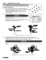
2.2
To attach threaded rod to top hanger bracket:
Assemble top hanger assembly (
diagram 2A
). Refer to
Chart 2A
for proper nut torque.
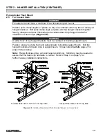
2.3
Bolt top hanger bracket assembly and beam clips to building support beam
(
diagram 2B
).
Note
:
Flange thickness may vary and require shimming. Shimming
may be needed to assure that the beam clip hardware is vertical.
TIP:
Standard top hanger brackets are designed for flange
widths from 1”-3”, 3-1/4”-5-1/4”, 5-1/2”-7-1/2”, 8”-10”.
WARNING
Threaded rod must have a minimum of two threads
beyond the hexnut.
Chart 2A.
Torque Chart.
4000#
250-2000#
Diagram 2A.
Attaching threaded rod to top hanger bracket.
WARNING
250-2000#
4000#
Diagram 2B.
Bolting top hanger bracket and beam clips to existing support beam.
2
9/05
“Center hole” of the top hanger bracket assembly must be centered on building support
beam.
Æ
Bridge Crane
Monorail
Bolt Diameter
1/2”
5/8”
3/4”
Torque
50 ft.-lb.
95 ft.-lb.
150 ft.lb.
TORQUE CHART
Содержание AL 1000
Страница 1: ......


