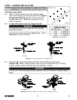


STEP 6 - HOIST TROLLEY INSTALLATION (CONTINUED)
Loadbar Hoist Trolley, 4000# Steel / 2000# - 4000# Aluminum
6.15
Clean inside flanges of track with a clean, dry cloth (
do
not use any kind of cleaning solution
) to remove grit
or debris that may have collected during shipping,
storage, or installation.
6.16
Be sure end stop is installed opposite the festooning end
of bridge/monorail.
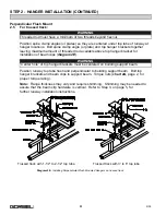
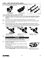
6.17
Bend
both legs
of all cotter pins (
diagram 6F
).
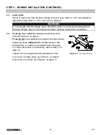
6.18
Attach hoist to hoist trolley by snapping hoist suspension hook over the clevis bolt (center
bolt) on hoist trolley loadbar.
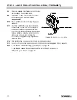
6.19
If hoist suspension hook is too large or hoist has a suspension device other than a hook,
you will need to remove clevis bolt and install suspension device (by others). Insert clevis
bolt back into place. Place nylock nut on end of bolt and tighten (
diagram 6G
).
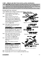
6.20
Roll hoist trolley into open end of track on bridge/monorail.
6.21
Install end stop on festooning end of bridge/monorail (
diagram 3C
, on page 6).
6.22
If you
do not
have festooning, go to Step 9, on page 21.
If you
do not
have a festoon stack section, go to Step 8, on page 18.
Otherwise go to Step 7, on page 17.
Diagram 6F.
Installing cotter pin
through trolley saddle clevis pin.
WARNING
Fully bend both legs of cotter pin (
diagram 6F
).
If cotter pin is cracked or fatigued it
must be replaced.
WARNING
Hang hoist from clevis bolt (center bolt) of hoist trolley only.
WARNING
Be sure to tighten nut on the clevis bolt (center bolt) of hoist trolley.
Do not “over-
tighten” nylock nut:
could cause damage to trolleys. Nylock nut on clevis bolt should
only be used once. If this item is disassembled, then nut must be replaced.
Diagram 6G.
Installing hoist on loadbar hoist trolley.
16
9/05
Содержание AL 1000
Страница 1: ......


