GORBEL AL 1000 Скачать руководство пользователя страница 13

STEP 5 - BRIDGE AND END TRUCK INSTALLATION (CONTINUED)

Extended End Trucks (continued)
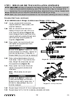
5.20

Place a wheel plate between the end truck
tubes.  Insert 1” dia. bolt into first tube,
through the wheel plate and out the
opposite tube (

diagram 5H

).

5.21

Place nylock nut on end of bolt and tighten
snug against extended end truck tube.

Note:

Wheel plates should pivot freely.

5.22

Repeat steps 5.20 and 5.21 for remaining wheel plate.

5.23

Repeat steps 5.17 to 5.22 for remaining extended end trucks.
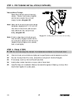
5.24

Slide an end truck over festooning end
of bridge (refer to the 

General

Arrangement Drawing

for exact end

truck location, end truck sleeve should
be 1” from first vertical) and clamp into
place (

diagram 5I

).

Note:

The festooning end of the bridge

will have a hole that is inset the same
or greater distance from the end of the
bridge than the hole in the opposite
end of the bridge.

5.25

Slide and position the non-clamping end
truck on the other end of bridge (refer to
the 

General Arrangement Drawing

for

exact location, end truck sleeve should be
1” from first vertical).

5.26

Go to Step 5.37, on page 13.

TIP:

ONLY ONE

end truck is clamped to the bridge: the other is not.  The clamping end truck

must be oriented with the festooning side of the track (refer to Step 8, on page 18 for
festooning). The non-clamping end truck allows adjustment for any runway misalignment.

TIP:

Extended end truck should be assembled before attaching to bridge.

Æ

Æ

Diagram 5I.  

Installing extended clamping end truck.

See 

TIP.

11

9/05

Diagram 5H.  

Installing wheel plates.

WARNING

Do not “over-tighten”

nylock nut:  could

cause damage to end trucks.  Nylock nut
can only be used once.  If this item is
disassembled, then nut must be replaced.

Содержание AL 1000

Страница 1: ......

Страница 2: ...Installation 14 16 Step 7 Festoon Stack Section Installation 17 Step 8 Festooning Installation 18 21 Step 9 Final Steps 21 Applied Forces to the Supporting Structure 22 Sway Bracing and Thrust Bracin...

Страница 3: ...ore you begin installing your crane 1 2 Check packing list to make sure correct quantity of parts is included 1 3 Tools and materials typically needed to assemble crane are as follows Hand tools Power...

Страница 4: ...Note Flange thickness may vary and require shimming Shimming may be needed to assure that the beam clip hardware is vertical TIP Standard top hanger brackets are designed for flange widths from 1 3 3...

Страница 5: ...rque nuts chart 2A page 2 for proper torque rating Note Sway brace brackets should be installed at this time see page 23 WARNING Do not over tighten clamping bolts on the lower hanger assemblies this...

Страница 6: ...upport beam Bolt top hanger brackets and beam clips to support beam Torque nuts chart 2A page 2 for proper torque rating Note Flange thickness may vary and require shimming Shimming may be needed to a...

Страница 7: ...B Torque nuts chart 2A page 2 for proper torque rating TIP The closer the runways monorails are to level and parallel the better the crane will perform WARNING Threaded rod must have a minimum of two...

Страница 8: ...ctions Install end stops diagram 3C molded bumper with through bolt in runway end opposite festooning end For more information on festooning refer to Step 8 on page 18 Tighten nut on through bolt unti...

Страница 9: ...trolley or end truck operation Tighten clamping bolts along the sides of splice joint to align track laterally Check to see that track portion of runway monorail is horizontally and vertically flush...

Страница 10: ...d diagram 5A Note The festooning end of the bridge will have a hole that is inset the same or greater distance from the end of the bridge than the hole in the opposite end of the bridge 5 5 Slide and...

Страница 11: ...n the other end of bridge refer to the General Arrangement Drawing for exact location 5 12 At both ends of bridge install a shear lug bolt in hole at top of bridge or in the coped brackets to prevent...

Страница 12: ...xtended end truck tubes support weldment wheel plates and required hardware 5 18 Slide an extended end truck tube halfway through each side of the end truck support weldment diagram 5F Insert a suppor...

Страница 13: ...hole that is inset the same or greater distance from the end of the bridge than the hole in the opposite end of the bridge 5 25 Slide and position the non clamping end truck on the other end of bridge...

Страница 14: ...lates should pivot freely 5 32 Repeat steps 5 30 and 5 31 for remaining wheel plate 5 33 Repeat steps 5 27 to 5 32 for remaining extended end trucks TIP ONLY ONE end truck is clamped to the bridge the...

Страница 15: ...grams 5N or 5O 5 38 Lift bridge up to runways and simultaneously insert end trucks into open ends of runways Make sure festooning end of bridge is oriented with festooning runway For information on fe...

Страница 16: ...ide washers on clevis pin and insert cotter pin through trolley saddle clevis pin diagrams 6A 6B and 6C 6 6 Bend back both legs of cotter pin diagram 6D 6 7 If a tow arm is not being utilized on the t...

Страница 17: ...hose between the two legs of the U bolt and festoon clamp plate Secure cable air hose by tightening nuts at the end of the U bolt forcing the festooning clamp plate snug against the cable air hose 6...

Страница 18: ...back into place Place nylock nut on end of bolt and tighten diagram 6G 6 20 Roll hoist trolley into open end of track on bridge monorail 6 21 Install end stop on festooning end of bridge monorail diag...

Страница 19: ...ld festoon stack section to runway monorail at locations diagram 7B Note Because trolleys are too large to roll under the end stop on the 250 and 500 series track the end stop and accompanying hardwar...

Страница 20: ...every 6 0 along runway monorail between bridge and festoon stack section 8 5 Slide festoon clamp into end of runway monorail festoon stack section diagram 8A Tighten clamp bolt until lockwasher is fl...

Страница 21: ...ck Remove end stop from festoon stack section festooning end of runway monorail 8 12 Roll festoon trolleys into end of runway monorail festoon stack section track on festooning side of runway monorail...

Страница 22: ...does not interfere with trolley body WARNING Crane cannot be utilized as a ground A separate ground wire is required For example systems with 3 phase power require 3 conductors plus one ground wire Di...

Страница 23: ...present in the hose and retighten Velcro straps so the vacuum hose is held tightly STEP 9 FINAL STEPS 9 1 Check to make sure all bolts are tightened to specifications and lockwashers are flat 9 2 Be s...

Страница 24: ...15 for hoist weight W Weight per foot of runway lb ft w Weight per foot of bridge lb ft Note If there are only 2 hangers per runway substitute L1 2 for L1 in the R1 formula Note For bridge lengths gre...

Страница 25: ...ual as shown in diagram 1 When attaching bracing to steel truss or steel beams the bracing member shall be attached to the top chord or top flange and located as close to the bridging members as possi...

Страница 26: ...hing wrong or apparently wrong the problem should be reported immediately to the proper supervisor and appropriate corrective action taken Operating Suggestions One measure of a good crane operator is...

Страница 27: ...respect for any reason Gorbel and Purchaser also agree that Purchaser has been put on notice that dealer or distributor is not authorized to incur any obligations or to make any representations or war...

Страница 28: ...ENANCE Check that lockwashers are compressed and nuts tightened to manufacturer s specifications Check that lockwashers are compressed and nuts tightened to manufacturer s specifications Check that lo...

Отзывы: