PART TWO - INSTALLATION
SECTION 3 - ELECTRICAL CONNECTIONS
Rev. 0-201
PRO-series Model C3 Conductivity Transmitter
25
+
1
2
3
4
5
6
7
-
Loop Resistance
(See nomograph)
Loop Power
14-30VDC
Jumper Required
200
0
14
16
18
R
ESIST
AN
C
E
IN
O
H
M
S
800
400
600
1000
1200
1400
DC VOLTAGE
20
22
24
26
28
30
50 Ohms/Volt
LOOP LOAD
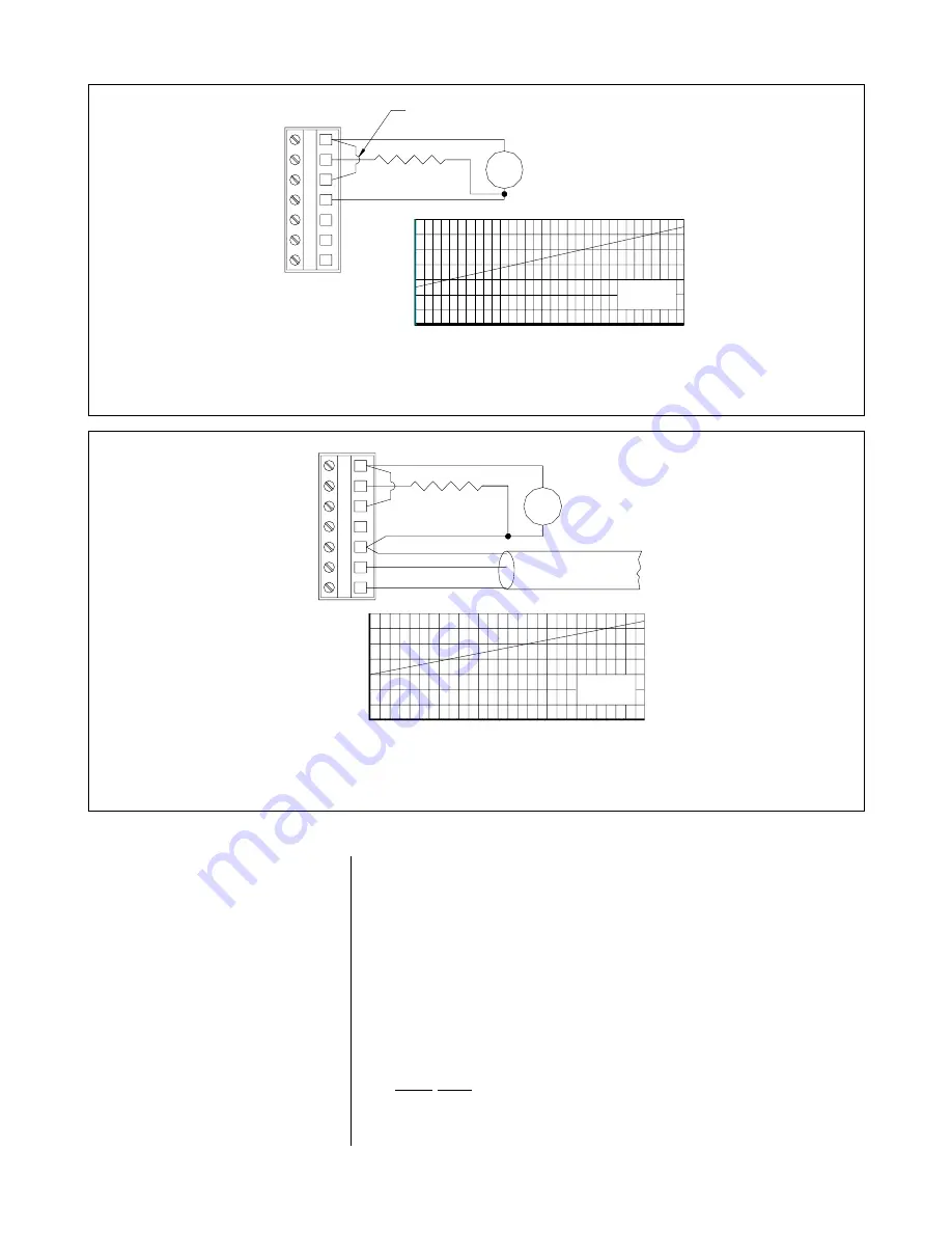
FIGURE 2-9 Three-wire Hookup -- Load Sourcing
RS-485 Serial
communications
Comms Return
"A" +
"B" -
+
1
2
3
4
5
6
7
-
Loop Resistance
(See nomograph)
Loop Power
16-30VDC
DC VOLTAGE
1000
R
E
SIS
T
AN
C
E
IN
O
H
M
S
400
0
200
600
800
1200
1400
16
18
20
22
LOOP LOAD
50 Ohms/Volt
26
24
28
30
FIGURE 2-10 Three-wire Hookup -- Load Sourcing with RS-485 Serial Communication
3.4 Four-wire Hookups
In a four-wire hookup, the transmitter can be wired two ways
depending on whether or not RS-485 serial communication
is used. At least 12 VDC is required for operation (16 VDC
with serial communication).
Depending on how the transmitter is mounted, route the DC
power, analog output, and RS-485 serial communication
wiring into the transmitter as follows:
•
Wall/Pipe-mounted Transmitter: Route cable through
right side cable entry knockout hole in the back cover.
•
Panel-mounted Transmitter: Route cable behind panel to
the exposed TB1 terminal strip.


