E44.X.01.6C-04
Mounting- and Operating Manual GIR 300
page 24 of 34
- Use button 2 and button 3 to set the desired value for the switching-delay of output 1.
Hint: The selected value [0.01 ... 2.00] will be in seconds.
-
Press button 1 to validate the selection. The display shows “
1.dEL
“ again.
-
When pressing button 1 again, the device will display “
1.Err
“ (preferred state of output 1).
- Use button 2 and button 3 (middle or right button) to set the desired initial state in case of an
error
.
Display
Preferred state of the out-
put
Notes
off
Inactive in case of an error
(contact is open)
on
Active in case of an error
(contact ist closed)
-
Press button 1 to validate the selection. The display shows “
1.Err
“ again.
- In case you selected a 3-point-controller you have to make the following settings similar to
the settings you already made for output 1:
“
2.dEL
“ (delay of output 2) and
“
2.Err
“ (preferred state of output 2).
Depending on the selected output function you have to make the settings for switching and alarm points.
See description in chapter
Fehler! Verweisquelle konnte nicht gefunden werden.
„
Fehler! Verweisquel-
le konnte nicht gefunden werden.
“ for further information.
Hint:
The settings for the switching and alarm points can be made later in an extra menu (see chapter
Fehler! Verweisquelle konnte nicht gefunden werden.
)
7
Switching points and alarm-boundaries
Note:
All relevant switching and alarm points can be set at this menu.
(Preferred output position and delay of the output can only be set at configuration menu)
Depending on the selected output function different parameters have to be adjusted.
The configuration menu automatically skips parameters not needed for the selected output
function.
Please note: The settings of the switching points and alarm-boundaries will automatically be reset
to factory default when any changes for the settings
„Func“, „Inp.1“ or „Unit“ had been
made!
General note:
The state of the switching contacts is displayed with 2 LED´s. LED “1” displays the state of the contact
of relay 1 and LED “2” displays the state of contact of relay 2. (LED illuminate = contact is closed)
Hint:
The buttons 2 and 3 are featured with a ‘roll-function‘. When pressing the button once the value will be
raised (button 2) by one or lowered (button 3) by one.
When holding the button pressed for longer than 1 sec. the value starts counting up or down, the counting
speed will be raised after a short period of time.
The device also features a ‘overflow-function‘, when reaching the upper limit of the range, the device
switches to the lower limit, vice versa.
Please note:
When you are configuring the device and don’t press
any button for more than 60 sec. the configuration of
the device will be cancelled.
The changes you made will not be saved and will be
lost!
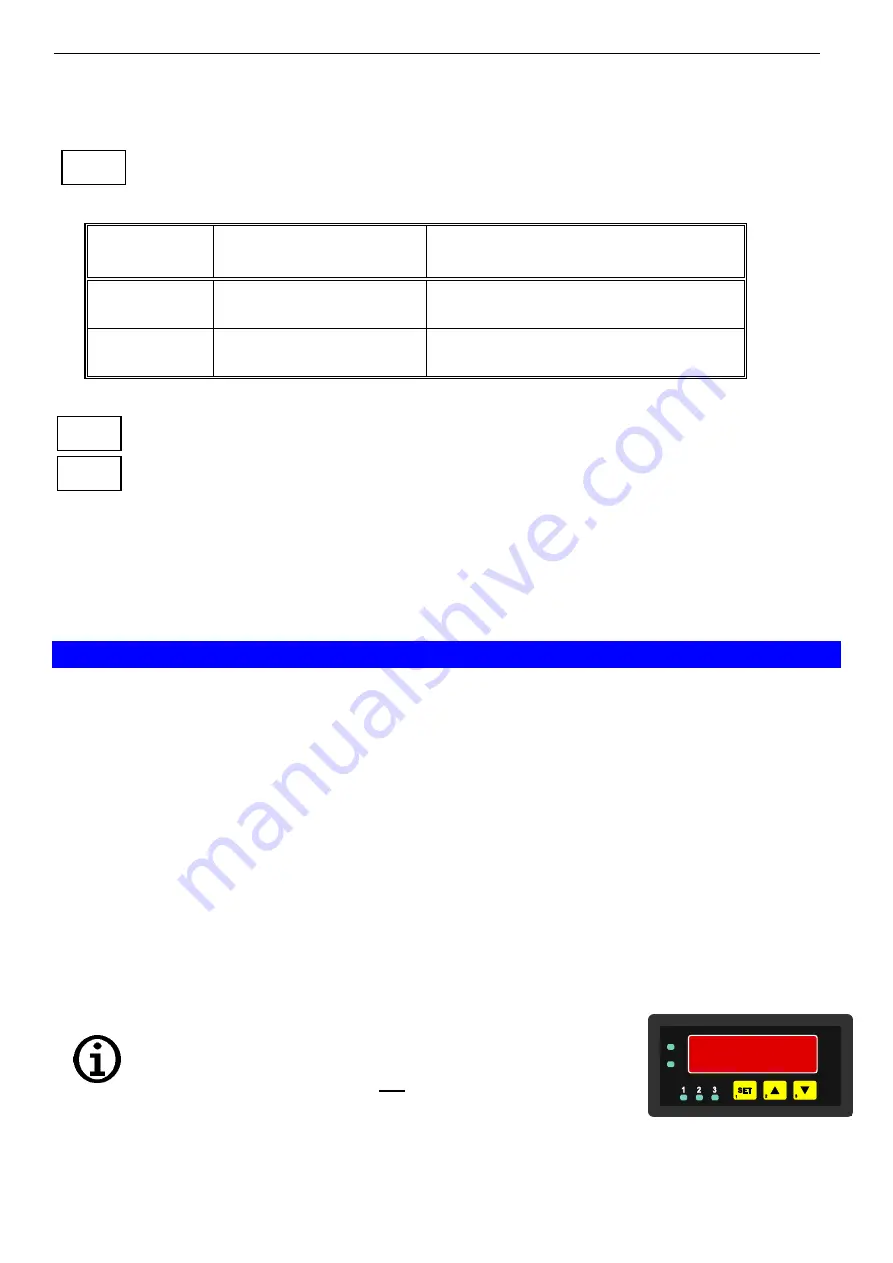
- When pressing button 1 for >2 sec. the menu to select the switching
points and alarm-boundaries will be called.
-
Depending on the configuration you have made in the „output“ menu
you will get different Display values.
Please follow the specific chapter for further information.
button 1 button 2 button 3
1.ERR
2.DEL
2.ERR


