Introduction
43
1
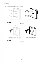
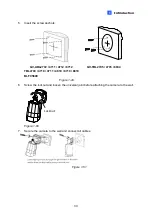
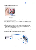
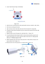
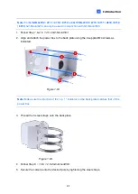
5. Position the power box on the
wall with the “up
↑
” indicator pointing up and align the
screw holes indicated below to the 4 mounting holes on the wall.
Figure 1-66
6. Secure the power box to the wall with the supplied long screws.
7. Thread the Ethernet cable through the center hole (proceed to Step 9) or through the
PG21 conduit connector and the power box as shown in No 8,
Figure 1-61
(proceed to
Step 8).
8. Rotate the plastic ring to secure the conduit connector to the power box. Secure in the
cap, as shown in No 9,
Figure 1-61
.
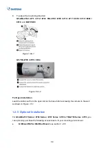
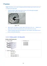
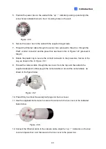
9. Thread the camera cable through the box cover from the top, and then attach the
supplied waterproof rubber plug to the camera cable at around the camera base, as
shown in the figure below.
Figure 1-67
10. Press firmly to embed the waterproof plug onto the box cover.
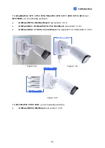
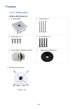
11. Use the supplied short screws to secure the camera to the box cover at the indicated
holes below.
Figure 1-68
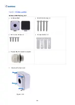
12. Connect the Ethernet cable to the camera cable, a
lign the “up
↑
” indicators on the box
cover and power box, and then secure the box cover to the power box.
Содержание CV-ADR2702
Страница 161: ...148 Figure 3 36 ...

