


3 - 38
Genie Z-60/34
Part No. 75861
November 2003
Section 3 • Scheduled Maintenance Procedures
REV A
CHECKLIST
C
PROCEDURES
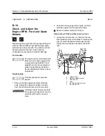
7 Carefully move the test weights to each
remaining location in the platform.
Result: The alarm should be sounding.
The platform overload indicator light should be
flashing at both the ground and platform
controls.
If the alarm does not sound and
the platform overload indicator light
does not come on with the test
weights in any of the platform
locations, the platform overload
system needs to be calibrated.
See D-6, How to Calibrate the
Platform Overload System.
There may be an approximate 2
second delay before the overload
indicator light turns on and the
alarm sounds.
8 Test all machine functions from the platform
controls.
Result: All platform control functions should not
operate.
9 Turn the key switch to ground control.
6 Add an additional 75 lbs./34 kg to the original
test weight to overload the platform based on
your maximum platform capacity:
Result: The alarm should be sounding.
The platform overload indicator light should be
flashing at both the ground and platform
controls.
If the alarm does not sound and
the platform overload indicator light
does not come on with the test
weights in any of the platform
locations, the platform overload
system needs to be calibrated.
See D-6, How to Calibrate the
Platform Overload System.
There may be an approximate 2
second delay before the overload
indicator light turns on and the
alarm sounds.
Содержание Z-60/34
Страница 1: ...Part No 75861 November 2003 Rev A Service Manual Refer to inside cover for serial number information ...
Страница 12: ...Genie Z 60 34 Part No 75861 November 2003 This page intentionally left blank ...
Страница 154: ...5 18 GenieZ 60 34 PartNo 75861 November 2003 Section 5 Fault Codes This page intentionally left blank ...
Страница 157: ......
Страница 160: ...Electrical Schematic Deutz F4L 1011F Models November 2003 Section 6 Schematics ...
Страница 162: ...Ground Control Box Wiring Diagram Deutz F4L 1011F Models November 2003 Section 6 Schematics ...
Страница 164: ...Platform Control Box Wiring Diagram Deutz F4L 1011F Models November 2003 Section 6 Schematics ...
Страница 165: ......
Страница 168: ...Electrical Schematic Ford LRG 425 EFI Models November 2003 Section 6 Schematics ...
Страница 170: ...Ground Control Box Wiring Diagram Ford LRG 425 EFI Models November 2003 Section 6 Schematics ...
Страница 172: ...Platform Control Box Wiring Diagram Ford LRG 425 EFI Models November 2003 Section 6 Schematics ...
Страница 173: ...November2003 Section 6 Schematics PartNo 75861 GenieZ 60 34 6 11 ...
Страница 176: ...Hydraulic Schematic 2WD Models before serial number 4461 November 2003 Section 6 Schematics ...
Страница 178: ...Hydraulic Schematic 4WD Models before serial number 4461 November 2003 Section 6 Schematics ...
Страница 180: ...Hydraulic Schematic 2WD Models after serial number 4460 November 2003 Section 6 Schematics ...
Страница 182: ...Hydraulic Schematic 4WD Models after serial number 4460 November 2003 Section 6 Schematics ...


