


Part No. 75861
Genie Z-60/34
3 - 25
November 2003
Section 3 • Scheduled Maintenance Procedures
REV A
4 Move the function enable toggle switch to the
high idle (rabbit symbol) position at the ground
controls.
Result: High idle should be 2300 rpm.
If high idle rpm is correct, disregard adjustment
step 5.
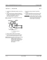
5 Loosen the yoke lock nut, then turn the high idle
adjustment nut and solenoid boot
counterclockwise to increase the rpm or
clockwise to decrease the rpm. Tighten the
yoke lock nut and recheck the rpm.
Result: High idle should be 2300 rpm.
Be sure the solenoid fully retracts
when activating high idle.
CHECKLIST
B
PROCEDURES
B-11
Test the Ground Control
Override
A properly functioning ground control override is
essential to safe machine operation. The ground
control override function is intended to allow ground
personnel to operate the machine from the ground
controls whether or not the red Emergency Stop
button on the platform controls is in the on or off
position. This function is particularly useful if the
operator at the platform controls cannot return the
boom to the stowed position.
1 Push in the platform red Emergency Stop button
to the off position.
2 Start the engine from the ground controls.
3 At the ground controls, operate each boom
function through a partial cycle.
Result: All boom functions should operate.
Содержание Z-60/34
Страница 1: ...Part No 75861 November 2003 Rev A Service Manual Refer to inside cover for serial number information ...
Страница 12: ...Genie Z 60 34 Part No 75861 November 2003 This page intentionally left blank ...
Страница 154: ...5 18 GenieZ 60 34 PartNo 75861 November 2003 Section 5 Fault Codes This page intentionally left blank ...
Страница 157: ......
Страница 160: ...Electrical Schematic Deutz F4L 1011F Models November 2003 Section 6 Schematics ...
Страница 162: ...Ground Control Box Wiring Diagram Deutz F4L 1011F Models November 2003 Section 6 Schematics ...
Страница 164: ...Platform Control Box Wiring Diagram Deutz F4L 1011F Models November 2003 Section 6 Schematics ...
Страница 165: ......
Страница 168: ...Electrical Schematic Ford LRG 425 EFI Models November 2003 Section 6 Schematics ...
Страница 170: ...Ground Control Box Wiring Diagram Ford LRG 425 EFI Models November 2003 Section 6 Schematics ...
Страница 172: ...Platform Control Box Wiring Diagram Ford LRG 425 EFI Models November 2003 Section 6 Schematics ...
Страница 173: ...November2003 Section 6 Schematics PartNo 75861 GenieZ 60 34 6 11 ...
Страница 176: ...Hydraulic Schematic 2WD Models before serial number 4461 November 2003 Section 6 Schematics ...
Страница 178: ...Hydraulic Schematic 4WD Models before serial number 4461 November 2003 Section 6 Schematics ...
Страница 180: ...Hydraulic Schematic 2WD Models after serial number 4460 November 2003 Section 6 Schematics ...
Страница 182: ...Hydraulic Schematic 4WD Models after serial number 4460 November 2003 Section 6 Schematics ...


