


Part No. 75861
Genie Z-60/34
3 - 29
November 2003
Section 3 • Scheduled Maintenance Procedures
REV A
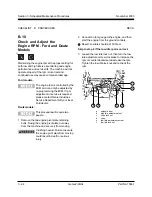
B-16
Test the Drive Brakes
Proper brake action is essential to safe machine
operation. The drive brake function should operate
smoothly, free of hesitation, jerking and unusual
noise. Hydrostatic brakes and hydraulically-
released individual wheel brakes can appear to
operate normally when they are actually not fully
operational.
Collision hazard. Be sure that the
machine is not in free-wheel or
partial free-wheel configuration.
Refer to B-8, Confirm the Proper
Brake Configuration.
Select a test area that is firm, level
and free of obstructions.
1 Mark a test line on the ground for reference.
2 Start the engine from the platform controls.
3 Move the engine idle control switch to
foot switch activated high idle (rabbit and
foot switch), then lower the boom into the
stowed position.
4 Choose a point on the machine; i.e., contact
patch of a tire, as a visual reference for use
when crossing the test line.
5 Bring the machine to top drive speed before
reaching the test line. Release the drive joystick
when your reference point on the machine
crosses the test line.
6 Measure the distance between the test line and
your machine reference point. Refer to
Section 2, Specifications.
The brakes must be able to hold
the machine on any slope it is able
to climb.
CHECKLIST
B
PROCEDURES
Содержание Z-60/34
Страница 1: ...Part No 75861 November 2003 Rev A Service Manual Refer to inside cover for serial number information ...
Страница 12: ...Genie Z 60 34 Part No 75861 November 2003 This page intentionally left blank ...
Страница 154: ...5 18 GenieZ 60 34 PartNo 75861 November 2003 Section 5 Fault Codes This page intentionally left blank ...
Страница 157: ......
Страница 160: ...Electrical Schematic Deutz F4L 1011F Models November 2003 Section 6 Schematics ...
Страница 162: ...Ground Control Box Wiring Diagram Deutz F4L 1011F Models November 2003 Section 6 Schematics ...
Страница 164: ...Platform Control Box Wiring Diagram Deutz F4L 1011F Models November 2003 Section 6 Schematics ...
Страница 165: ......
Страница 168: ...Electrical Schematic Ford LRG 425 EFI Models November 2003 Section 6 Schematics ...
Страница 170: ...Ground Control Box Wiring Diagram Ford LRG 425 EFI Models November 2003 Section 6 Schematics ...
Страница 172: ...Platform Control Box Wiring Diagram Ford LRG 425 EFI Models November 2003 Section 6 Schematics ...
Страница 173: ...November2003 Section 6 Schematics PartNo 75861 GenieZ 60 34 6 11 ...
Страница 176: ...Hydraulic Schematic 2WD Models before serial number 4461 November 2003 Section 6 Schematics ...
Страница 178: ...Hydraulic Schematic 4WD Models before serial number 4461 November 2003 Section 6 Schematics ...
Страница 180: ...Hydraulic Schematic 2WD Models after serial number 4460 November 2003 Section 6 Schematics ...
Страница 182: ...Hydraulic Schematic 4WD Models after serial number 4460 November 2003 Section 6 Schematics ...


