


Schematics
Observe and Obey:
Troubleshooting and repair procedures shall be
completed by a person trained and qualified on
the repair of this machine.
Immediately tag and remove from service a
damaged or malfunctioning machine.
Repair any machine damage or malfunction
before operating the machine.
Before Troubleshooting:
Read, understand and obey the safety rules
and operating instructions printed in the
Genie Z-60/34 Operator's Manual.
Be sure that all necessary tools and test
equipment are available and ready for use.
About This Section
There are two groups of schematics in this section.
An illustration legend precedes each group of
drawings.
Electrical Schematics
Electrocution hazard. Contact with
electrically charged circuits could
result in death or serious injury.
Remove all rings, watches and
other jewelry.
Hydraulic Schematics
Bodily injury hazard. Spraying
hydraulic oil can penetrate and
burn skin. Loosen hydraulic
connections very slowly to allow
the oil pressure to dissipate
gradually. Do not allow oil to squirt
or spray.
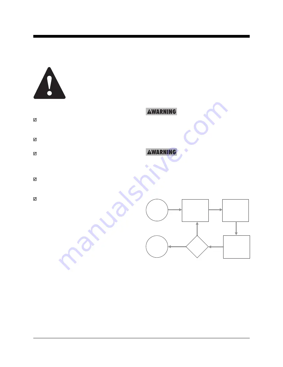
General Repair Process
Malfunction
discovered
Identify
symptoms
Troubleshoot
Perform
repair
Return to
service
problem
solved
problem
still exists
Inspect
and test
Part No. 75861
Genie Z-60/34
6 - 1
Section 6 • Schematics
November 2003
Содержание Z-60/34
Страница 1: ...Part No 75861 November 2003 Rev A Service Manual Refer to inside cover for serial number information ...
Страница 12: ...Genie Z 60 34 Part No 75861 November 2003 This page intentionally left blank ...
Страница 154: ...5 18 GenieZ 60 34 PartNo 75861 November 2003 Section 5 Fault Codes This page intentionally left blank ...
Страница 157: ......
Страница 160: ...Electrical Schematic Deutz F4L 1011F Models November 2003 Section 6 Schematics ...
Страница 162: ...Ground Control Box Wiring Diagram Deutz F4L 1011F Models November 2003 Section 6 Schematics ...
Страница 164: ...Platform Control Box Wiring Diagram Deutz F4L 1011F Models November 2003 Section 6 Schematics ...
Страница 165: ......
Страница 168: ...Electrical Schematic Ford LRG 425 EFI Models November 2003 Section 6 Schematics ...
Страница 170: ...Ground Control Box Wiring Diagram Ford LRG 425 EFI Models November 2003 Section 6 Schematics ...
Страница 172: ...Platform Control Box Wiring Diagram Ford LRG 425 EFI Models November 2003 Section 6 Schematics ...
Страница 173: ...November2003 Section 6 Schematics PartNo 75861 GenieZ 60 34 6 11 ...
Страница 176: ...Hydraulic Schematic 2WD Models before serial number 4461 November 2003 Section 6 Schematics ...
Страница 178: ...Hydraulic Schematic 4WD Models before serial number 4461 November 2003 Section 6 Schematics ...
Страница 180: ...Hydraulic Schematic 2WD Models after serial number 4460 November 2003 Section 6 Schematics ...
Страница 182: ...Hydraulic Schematic 4WD Models after serial number 4460 November 2003 Section 6 Schematics ...


