


Part No. 75861
Genie Z-60/34
4 - 41
November 2003
Section 4 • Repair Procedures
REV A
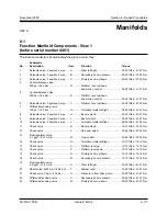
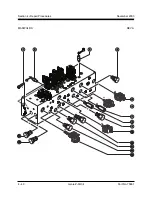
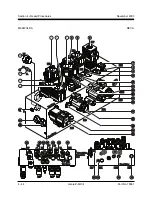
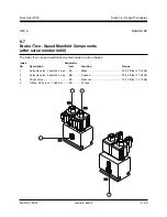
8-3
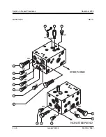
Function Manifold Components
(after serial number 4460)
The function manifold is located behind the ground control box.
Schematic
No.
Description
Item
Function
Torque
1
Solenoid valve, 3 position 4 way ....... HA ........ Turntable rotate left/right ................... 20-25 ft-lbs / 27-34 Nm
2
Differential sensing valve,
150 psi / 10.3 bar ............................... HB ........ Turntable rotate left/right ................... 30-35 ft-lbs / 41-47 Nm
3
Solenoid valve, 3 position 4 way ....... HC ........ Platform level up/down .................... 20-25 ft-lbs / 27-34 Nm
4
Solenoid valve, 3 position 4 way ....... HD ........ Primary boom up/down ..................... 20-25 ft-lbs / 27-34 Nm
5
Solenoid valve, 3 position 4 way ....... HE ........ Secondary boom up/down ................ 20-25 ft-lbs / 27-34 Nm
6
Solenoid valve, 3 position 4 way ....... HF ......... Steer left/right .................................... 30-35 ft-lbs / 41-47 Nm
7
Check valve, 50 psi / 3.45 bar ........... HG ........ Pressure in from drive pump ............. 30-35 ft-lbs / 41-47 Nm
8
Diagnostic nipple ............................... HH ........ Testing
9
Flow regulator valve,
3.5 gpm / 13.2 L/min .......................... HI .......... Steer left/right .................................... 30-35 ft-lbs / 41-47 Nm
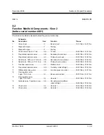
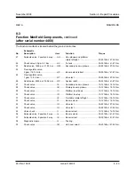
10
Differential sensing valve .................. HJ ......... Secondary boom up/down ................ 30-35 ft-lbs / 41-47 Nm
11
Differential sensing valve .................. HK ........ Primary boom up/down ..................... 30-35 ft-lbs / 41-47 Nm
12
Counterbalance valve,
500 psi / 34.4 bar ............................... HL ......... Platform level up/down
and motion control ............................ 30-35 ft-lbs / 41-47 Nm
13
Proportional solenoid valve ............... HM ........ Secondary boom down ..................... 20-25 ft-lbs / 27-34 Nm
14
Counterbalance valve,
500 psi / 34.4 bar ............................... HN ........ Platform level up/down
and motion control ............................ 30-35 ft-lbs / 41-47 Nm
15
Proportional solenoid valve ............... HO ........ Primary boom down .......................... 20-25 ft-lbs / 27-34 Nm
16
Relief valve, 1800 psi / 124.1 bar ...... HP ........ Primary boom up/down ..................... 20-25 ft-lbs / 27-34 Nm
17
Free flow needle valve ...................... HQ ........ Platform level .................................... 20-25 ft-lbs / 27-34 Nm
18
Proportional solenoid valve ............... HR ........ Turntable rotate left/right ................... 20-25 ft-lbs / 27-34 Nm
19
Flow regulator valve,
0.1 gpm / 0.37 L/min .......................... HS ........ Flow control ....................................... 20-25 ft-lbs / 27-34 Nm
20
Differential sensing valve .................. HT ......... Function pressure control ................. 30-35 ft-lbs / 41-47 Nm
This parts list continues. Please turn the page.
MANIFOLDS
Содержание Z-60/34
Страница 1: ...Part No 75861 November 2003 Rev A Service Manual Refer to inside cover for serial number information ...
Страница 12: ...Genie Z 60 34 Part No 75861 November 2003 This page intentionally left blank ...
Страница 154: ...5 18 GenieZ 60 34 PartNo 75861 November 2003 Section 5 Fault Codes This page intentionally left blank ...
Страница 157: ......
Страница 160: ...Electrical Schematic Deutz F4L 1011F Models November 2003 Section 6 Schematics ...
Страница 162: ...Ground Control Box Wiring Diagram Deutz F4L 1011F Models November 2003 Section 6 Schematics ...
Страница 164: ...Platform Control Box Wiring Diagram Deutz F4L 1011F Models November 2003 Section 6 Schematics ...
Страница 165: ......
Страница 168: ...Electrical Schematic Ford LRG 425 EFI Models November 2003 Section 6 Schematics ...
Страница 170: ...Ground Control Box Wiring Diagram Ford LRG 425 EFI Models November 2003 Section 6 Schematics ...
Страница 172: ...Platform Control Box Wiring Diagram Ford LRG 425 EFI Models November 2003 Section 6 Schematics ...
Страница 173: ...November2003 Section 6 Schematics PartNo 75861 GenieZ 60 34 6 11 ...
Страница 176: ...Hydraulic Schematic 2WD Models before serial number 4461 November 2003 Section 6 Schematics ...
Страница 178: ...Hydraulic Schematic 4WD Models before serial number 4461 November 2003 Section 6 Schematics ...
Страница 180: ...Hydraulic Schematic 2WD Models after serial number 4460 November 2003 Section 6 Schematics ...
Страница 182: ...Hydraulic Schematic 4WD Models after serial number 4460 November 2003 Section 6 Schematics ...


