


3 - 26
Genie Z-60/34
Part No. 75861
November 2003
Section 3 • Scheduled Maintenance Procedures
REV A
a
b
c
d
B-13
Test the Platform Self-leveling
Automatic platform self-leveling throughout
the full cycle of boom raising and lowering is
essential for safe machine operation. The
platform is maintained at level by the platform
leveling slave cylinder which operates in a closed
loop hydraulic circuit with the master cylinder
located at the base of the boom.
A platform self-leveling failure creates an unsafe
working condition for platform and
ground personnel.
1 Start the engine from the ground controls and
lower the boom into the stowed position.
2 Hold the function enable toggle switch to either
side and adjust the platform to a level position
using the platform level toggle switch.
3 Raise and lower the primary boom through
a full cycle.
Result: The platform should remain level at
all times to within ±5 degrees.
B-12
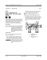
Check the Directional Valve
Linkage
Perform this test only on models
equipped with a oscillating axle.
Proper axle oscillation is essential to safe machine
operation. If the directional valve linkage is not
operating correctly, the stability of the machine is
compromised and it may tip over.
1 Remove the drive chassis cover and the axle
covers from the non-steer end of the drive
chassis.
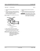
2 Locate the directional valve inside of the non-
steer axle and inspect the linkage for the
following:
· Lock nut is tight against yoke
· Yoke clevis pins are installed
· Cotter pins are installed through clevis pins
· Linkage is properly attached to
directional valve
a
directional valve
b
clevis pin with cotter pin (hidden)
c
yoke
d
lock nut
CHECKLIST
B
PROCEDURES
Содержание Z-60/34
Страница 1: ...Part No 75861 November 2003 Rev A Service Manual Refer to inside cover for serial number information ...
Страница 12: ...Genie Z 60 34 Part No 75861 November 2003 This page intentionally left blank ...
Страница 154: ...5 18 GenieZ 60 34 PartNo 75861 November 2003 Section 5 Fault Codes This page intentionally left blank ...
Страница 157: ......
Страница 160: ...Electrical Schematic Deutz F4L 1011F Models November 2003 Section 6 Schematics ...
Страница 162: ...Ground Control Box Wiring Diagram Deutz F4L 1011F Models November 2003 Section 6 Schematics ...
Страница 164: ...Platform Control Box Wiring Diagram Deutz F4L 1011F Models November 2003 Section 6 Schematics ...
Страница 165: ......
Страница 168: ...Electrical Schematic Ford LRG 425 EFI Models November 2003 Section 6 Schematics ...
Страница 170: ...Ground Control Box Wiring Diagram Ford LRG 425 EFI Models November 2003 Section 6 Schematics ...
Страница 172: ...Platform Control Box Wiring Diagram Ford LRG 425 EFI Models November 2003 Section 6 Schematics ...
Страница 173: ...November2003 Section 6 Schematics PartNo 75861 GenieZ 60 34 6 11 ...
Страница 176: ...Hydraulic Schematic 2WD Models before serial number 4461 November 2003 Section 6 Schematics ...
Страница 178: ...Hydraulic Schematic 4WD Models before serial number 4461 November 2003 Section 6 Schematics ...
Страница 180: ...Hydraulic Schematic 2WD Models after serial number 4460 November 2003 Section 6 Schematics ...
Страница 182: ...Hydraulic Schematic 4WD Models after serial number 4460 November 2003 Section 6 Schematics ...


