Part No. 29487
Genie Z-45/22
7 - 3
Service Manual - First Edition
Section 7 - Repair Procedures
2.50V DC
5.02V DC
25-29 seconds
4.33V DC
33-37 seconds
PLATFORM CONTROLS
8 Set the dual (lo) range: Press down the foot
switch, then move the control handle all the
way to the
down position. Adjust the voltage to
4.33V DC. Turn the dual range trimpot
adjustment screw clockwise to increase the
voltage or counterclockwise to decrease the
voltage.
7 Start the engine and move the engine speed
control switch to foot switch activated high idle
(rabbit and foot switch symbol). Raise the
primary boom 1 inch (2.5cm) above the drive
limit switch.
Engine should be at normal
operating temperature.
8 Start a timer and record how long it takes for
the primary boom to reach the
full up position.
Adjust the max-out trimpot to achieve a 25 to
29 second cycle time.
9 Start a timer and record how long it takes for
the primary boom to lower into the
full down
position. Adjust the dual range trimpot to
achieve a 33 to 37 second cycle time.
Specifications - Primary Boom Up/Down Function
Threshold
Primary boom up -
Max-out time
Primary boom down -
Dual range time
Primary Boom Extend/Retract
Controller Adjustments
1 Check the battery condition with a volt meter.
The reading should be 12V DC or more to
accurately adjust the controller.
2 Turn the key switch to platform control and pull
the Emergency Stop button to the
on position
at both the ground and platform controls. Do
not start the engine.
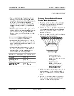
3 Open the platform control box lid and locate the
primary extend/retract controller.
a
dual (lo) adjustable trimpot
b
ramp rate adjustable trimpot
c
terminal "R" - activates max-out range
d
terminal unused
e
terminal "X" auxiliary
f
terminal "-" - ground
g
terminal "+" - battery, positive
h
terminal "A" - proportional output
i
threshold adjustable trimpot
j
max-out adjustable trimpot
4 Set the ramp rate: Turn the trimpot adjustment
screw clockwise 15 turns or until you hear a
click, then turn the screw counterclockwise 5
turns.
5 Connect the red lead(+) from a volt meter to
the “A” terminal on the controller PC board.
Connect the black lead(-) to ground.
a
b
c
d
e
f
g
h
i
j
Содержание Z-45/22
Страница 1: ...Technical Publications First Edition Part No 29487 Service Manual Z 45 22 ...
Страница 65: ...Part No 29487 Genie Z 45 22 4 39 Service Manual First Edition Section 4 Scheduled Maintenance Procedures ...
Страница 66: ...4 40 Genie Z 45 22 Part No 29487 Service Manual First Edition Section 4 Scheduled Maintenance Procedures ...
Страница 121: ...6 3 ...
Страница 122: ......
Страница 123: ...6 5 ...
Страница 124: ...6 6 ...
Страница 125: ...6 7 ...
Страница 126: ...6 8 ...
Страница 127: ......
Страница 128: ...6 10 ...
Страница 129: ...6 11 ...
Страница 130: ...6 12 ...
Страница 132: ...Z45 22 Hyd Index ...
Страница 133: ...Z45 22 Hyd Index ...
Страница 134: ...Z45 22 Hyd Index ...
Страница 135: ...Z45 22 Hyd Index ...
Страница 136: ...Z45 22 Hyd Index ...
Страница 137: ...Z45 22 Hyd Index ...


