7 - 28
Genie Z-45/22
Part No. 29487
Service Manual - First Edition
Section 7 - Repair Procedures
6-1
Timing Adjustment
Complete information to perform this procedure is
available in the Kubota V1702-B Diesel Engine
Workshop Manual (Kubota code number: 97897-
00691). Genie part number 29587.
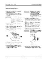
How to Install the Flex Plate
1 Install the flex plate onto the flywheel with the
raised spline against the flywheel.
2 Install the coupler onto the pump shaft with the
set screw towards the pump. Leave a 1/4 inch
(0.635mm) gap between the coupler and pump
end plate.
3 Apply removable Loctite
®
removable thread
sealant to the coupler set screw. Torque the
set screw to 36 ft-lbs (49 Nm).
Component damage hazard. Do
not force the drive pump during
re-installation or the flex plate
teeth may become damaged.
6-5
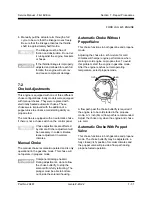
Water Temperature and Oil
Pressure Switches
The water temperature switch is a normally open
switch that closes at approximately 225° F
(107° C). When this switch closes, the engine is
shut off to prevent damage and will not restart until
the temperature drops below the switch point. An
over-temperature indicator light at the ground at
platform controls should turn on when the switch
closes.
Component damage hazard. Do
not crank the engine with the
over-temperature light on.
The oil pressure switch is a normally closed switch
that opens at approximately 7.1 psi (0.5 bar). If the
oil pressure drops below the switch point, the
switch closes and shuts off the engine. A low oil
pressure indicator light at the ground and platform
controls should turn on when the switch closes.
Component damage hazard. Do
not start or continue to run the
engine with the low oil pressure
light on.
6-3
RPM Adjustment
See the scheduled maintenance procedure B-13,
Check and Adjust the Engine RPM.
6-4
Flex Plate
The flex plate acts as a coupler between the
engine and the pump. It is bolted to the engine
flywheel and has a splined center to drive the
pump.
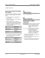
How to Remove the Flex Plate
1 Disconnect the wiring plug at the electronic
displacement controller (EDC), located on the
drive pump.
2 Support the drive pump with an appropriate
lifting device. Then remove all of the pump
mounting plate to engine bell housing bolts.
3 Carefully pull the pump away from the engine
and secure it from moving.
4 Remove the flex plate mounting fasteners, then
remove the flex plate from the engine.
Kubota V1702-B Engine
6-2
Glow Plugs
How to Check the Glow Plugs
See the scheduled maintenance procedure B-11,
Check The Glow Plugs - Diesel Models.
Содержание Z-45/22
Страница 1: ...Technical Publications First Edition Part No 29487 Service Manual Z 45 22 ...
Страница 65: ...Part No 29487 Genie Z 45 22 4 39 Service Manual First Edition Section 4 Scheduled Maintenance Procedures ...
Страница 66: ...4 40 Genie Z 45 22 Part No 29487 Service Manual First Edition Section 4 Scheduled Maintenance Procedures ...
Страница 121: ...6 3 ...
Страница 122: ......
Страница 123: ...6 5 ...
Страница 124: ...6 6 ...
Страница 125: ...6 7 ...
Страница 126: ...6 8 ...
Страница 127: ......
Страница 128: ...6 10 ...
Страница 129: ...6 11 ...
Страница 130: ...6 12 ...
Страница 132: ...Z45 22 Hyd Index ...
Страница 133: ...Z45 22 Hyd Index ...
Страница 134: ...Z45 22 Hyd Index ...
Страница 135: ...Z45 22 Hyd Index ...
Страница 136: ...Z45 22 Hyd Index ...
Страница 137: ...Z45 22 Hyd Index ...


