7 - 62
Genie Z-45/22
Part No. 29487
Service Manual - First Edition
Section 7 - Repair Procedures
50 in-lbs / 6 Nm
13 ft-lbs / 18 Nm
18 ft-lbs / 24 Nm
50 ft-lbs / 68 Nm
55 ft-lbs / 75 Nm
75 ft-lbs / 102 Nm
19-1
2WD Drive Manifold Components
Index
Schematic
No.
Description
Item
Function
Torque
1
Check valve ................................. M .................... Brake check .......................... 25-30 ft-lbs / 34-41 Nm
2
2 position 3 way valve ................. O .................... Brake release ........................ 8-10 ft-lbs / 11-14 Nm
3
2 position 3 way valve ................. N ..................... 2-Speed wheel motors,
(energized in high range to
destroke the rear motor
swash plates ......................... 8-10 ft-lbs / 11-14 Nm
4
Orifice 0.036 in (0.914mm) ......... P ..................... Motor shift / brake release circuit
5
Pilot to open check valve ............ E ..................... Right check in forward .......... 85-90 ft-lbs / 115-122 Nm
6
Pilot to open check valve ............ G .................... Right check in reverse .......... 85-90 ft-lbs / 115-122 Nm
7
Shuttle valve 3 position 3 way .... K ..................... Low pressure flow path for
brake release and 2-speed
motor shift ............................. 15-18 ft-lbs / 20-24 Nm
8
Pilot to open check valve ............ D ..................... Left check in reverse ............. 85-90 ft-lbs / 115-122 Nm
9
Pilot to open check valve ............ B ..................... Left check in forward ............. 85-90 ft-lbs / 115-122 Nm
10
2 position 3 way valve ................. J ..................... Energized in high range to
pilot open check valves
5,6, 8 & 9 to bypass flow
regulators and allow full
flow to front wheel motors ..... 8-10 ft-lbs / 11-14 Nm
11
Shuttle valve 2 position 3 way ..... I ..................... High pressure flow path for
flow regulator bypass ............ 10-13 ft-lbs / 14-18 Nm
12
Flow regulator valve .................... A ..................... Left flow control in forward .... 10-12 ft-lbs / 14-16 Nm
13
Flow regulator valve .................... C ..................... Left flow control in reverse .... 10-12 ft-lbs / 14-16 Nm
14
Relief valve, 320 psi (22 bar) ...... L ..................... Charge pressure ................... 10-12 ft-lbs / 14-16 Nm
15
Flow regulator valve .................... H ..................... Right flow control in reverse . 10-12 ft-lbs / 14-16 Nm
16
Flow regulator valve .................... F ..................... Right flow control in forward . 10-12 ft-lbs / 14-16 Nm
2WD Drive Manifold
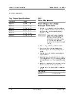
Plug Torque Specifications
Description
Torque
SAE No. 2
SAE No. 4
SAE No. 6
SAE No. 8
SAE No. 10
SAE No. 12
Содержание Z-45/22
Страница 1: ...Technical Publications First Edition Part No 29487 Service Manual Z 45 22 ...
Страница 65: ...Part No 29487 Genie Z 45 22 4 39 Service Manual First Edition Section 4 Scheduled Maintenance Procedures ...
Страница 66: ...4 40 Genie Z 45 22 Part No 29487 Service Manual First Edition Section 4 Scheduled Maintenance Procedures ...
Страница 121: ...6 3 ...
Страница 122: ......
Страница 123: ...6 5 ...
Страница 124: ...6 6 ...
Страница 125: ...6 7 ...
Страница 126: ...6 8 ...
Страница 127: ......
Страница 128: ...6 10 ...
Страница 129: ...6 11 ...
Страница 130: ...6 12 ...
Страница 132: ...Z45 22 Hyd Index ...
Страница 133: ...Z45 22 Hyd Index ...
Страница 134: ...Z45 22 Hyd Index ...
Страница 135: ...Z45 22 Hyd Index ...
Страница 136: ...Z45 22 Hyd Index ...
Страница 137: ...Z45 22 Hyd Index ...


