GE M
EDICAL
S
YSTEMS
D
IRECTION
2392751-100, R
EVISION
3
V
IVID
™ 4 S
ERVICE
M
ANUAL
8-116
Section 8-8 - Peripherals
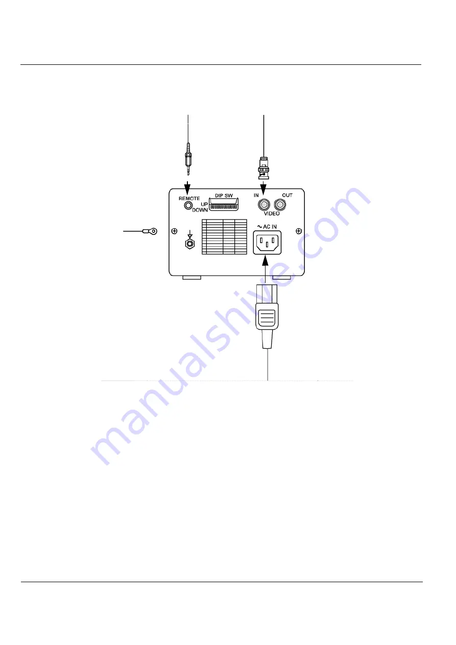
2.) Connect the Remote cable, the B/W Video IN cable, and the Power cable, as shown in
3.) Place the B/W printer in its correct final position.
4.) Secure the B/W printer by fastening the belt around it, or together with the VCR (if present).
5.) If more secure fastening is desired, install the optional shelf (P/N H45011CN), which can be ordered
separately if the Color Printer option is not installed
.
6.) Re-install the Connectors Panels Cover as described in the
Connector Panels Cover Installation
7) Reconnect the mains AC power cable from the wall outlet.
8) Turn ON the main circuit breaker located on rear of the Vivid™ 4.
9) Turn ON the Vivid™ 4 by pressing the ON/OFF button on the Control Console.
10.)Select the activation key under System Configuration, VCR/ECG Tab, A/B Swap.
By default, Print B key will be B&W Video printer and Print A key will be Color Video printer. For
more information on switching printer settings, see
Figure 8-103 B/W Video Printer Connection Cables
Remote cable:
From: Left Connectors Panel,
Print Trig
To: REMOTE
Video IN Cable:
From: Left Connectors Panel,
B/W Video OUT
To: VIDEO IN
Power cable
From: Right Connectors Panel, AC outlet
To: AC IN


