Chapter 8 - Replacement Procedures
8-141
D
IRECTION
5771498-100, R
EVISION
6
V
ENUE
™ S
ERVICE
M
ANUAL
P R E L I M I N A R Y
8-7-6-5
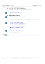
ON/OFF Switch Cable Installation Procedure
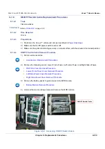
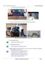
1.) Connect the ON/OFF Switch cable connector to the MPB J10 connector.
2.) Connect the other ON/OFF Switch cable connector to the MPB module by pressing the securing
clips on both sides of the connector.
3.) Install the MPB module and tighten the two mounting screws.
4.) Install the battery pack units.
5.) Refit the following covers: Lower Front eTower, left side eTower, Right side eTower and RS Probe
cover.
6.) Install all accessories.
7.) Turn ON power to the system.
•
Battery Module Installation Procedure
•
Left Side eTower Cover Installation Procedure
•
Right Side eTower Cover Installation Procedure
•
Lower Front eTower Cover Installation Procedure
•
RS Probe Cover Installation Procedure
•
Accessories - Replacement Procedures
Содержание Venue R1
Страница 477: ......


