8-30
Section 8-4 - System Modules- Replacement Procedures
D
IRECTION
5771498-100, R
EVISION
6
V
ENUE
™ S
ERVICE
M
ANUAL
P R E L I M I N A R Y
8-4-2-5
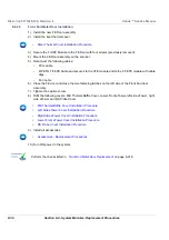
Front End Metal Door Installation
1.) Install the new FE Door assembly.
2.) Install the riser thermal cover.
3.) Secure the Full FE Module to the FE Door with four screws (previously removed).
4.) Mount the FE Door assembly on the scanner.
5.) Reconnect the following cables:
•
PCIe cable
•
MPB TO T-FEPS Cable and secure it to the CFE module and to the T-FEPS module with cable
clips.
•
Fan cable
6.) Close the FE door and close the two fastening latches on the left side of the Front End door
assembly.
7.) Tighten the captive screw.
8.) Refit the following covers: Mid Thermal Baffle Cover, Lower Front eTower, left side eTower, right
side eTower and RS Probe Cover.
9.) Install all accessories.
10.)Turn ON power to the system.
•
Riser Thermal Cover Installation Procedure
•
Mid Thermal Baffle Cover Installation Procedure
•
Left Side eTower Cover Installation Procedure
•
Right Side eTower Cover Installation Procedure
•
Lower Front eTower Cover Installation Procedure
•
RS Probe Cover Installation Procedure
•
Accessories - Replacement Procedures
Содержание Venue R1
Страница 477: ......

