


CHAPTER 7: TESTING
489 GENERATOR MANAGEMENT RELAY – INSTRUCTION MANUAL
7–13
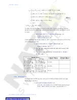
7.3.2
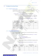
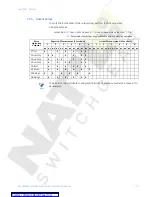
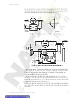
Power Measurement Test
The specification for reactive and apparent power is
±
1% of
×
2
×
CT
×
VT
ratio
×
VT
full-
scale
at
I
avg
<
2
×
CT. Perform the steps below to verify accuracy.
Z
In the
S2 SYSTEM SETUP
Z
CURRENT SENSING
menu, set:
PHASE CT PRIMARY:
“1000”
Z
In the
S2 SYSTEM SETUP
ZV
VOLTAGE SENSING
menu, set:
VT CONNECTION TYPE:
“Wye”
VOLTAGE TRANSFORMER RATIO:
“10.00:1”
Z
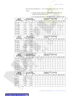
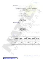
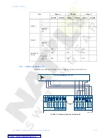
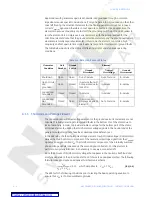
Inject current and apply voltage as per the table below.
Z
Verify accuracy of the measured values.
Z
View the measured values in the
A2 METERING DATA
ZV
POWER
METERING
menu:
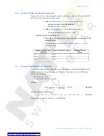
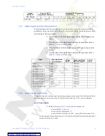
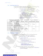
7.3.3
Reactive Power Accuracy
The specification for reactive power is
±
1% of
×
2
×
CT
×
VT
ratio
×
VT
full scale
at
I
avg
<
2
×
CT. Perform the steps below to verify accuracy and trip element.
Z
In the
S2 SYSTEM SETUP
Z
CURRENT SENSING
menu, set:
PHASE CT PRIMARY:
“5000”
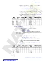
Z
In the
S2 SYSTEM SETUP
ZV
VOLTAGE SENSING
menu, set:
VT CONNECTION TYPE:
“Wye”
VOLTAGE TRANSFORMER RATIO:
“100:1”
Z
In the
S2 SYSTEM SETUP
ZV
GEN. PARAMETERS
menu, set
GENERATOR RATED MVA:
“100”
GENERATOR RATED POWER FACTOR:
“0.85”
GENERATOR VOLTAGE PHASE-PHASE:
“12000”
The rated reactive power is
.
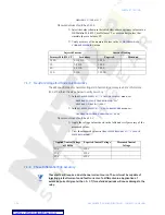
Z
Alter the following reactive power setpoints in the
S7 POWER ELEMENTS
Z
REACTIVE POWER
menu:
3
Injected Current / Applied Voltage
(Ia is the reference vector)
Power Quantity
Power Factor
1 A UNIT
5 A UNIT
Expected
Tolerance
Measured
Expected
Measured
Ia = 1 A
∠
0°
Ib = 1 A
∠
120° lag
Ic = 1 A
∠
240° lag
Va = 120 V
∠
342° lag
Vb = 120 V
∠
102° lag
Vc = 120 V
∠
222° lag
Ia = 5 A
∠
0°
Ib = 5 A
∠
120° lag
Ic = 5 A
∠
240° lag
Ia = 120 V
∠
342° lag
Vb = 120 V
∠
102° lag
Vc = 120 V
∠
222° lag
+3424 kW
3355 to
3493 kW
0.95 lag
Ia = 1 A
∠
0°
Ib = 1 A
∠
120° lag
Ic = 1 A
∠
240° lag
Va = 120 V
∠
288° lag
Vb = 120 V
∠
48° lag
Vc = 120 V
∠
168° lag
Ia = 5 A
∠
0°
Ib = 5 A
∠
120° lag
Ic = 5 A
∠
240° lag
Va = 120 V
∠
288° lag
Vb = 120 V
∠
48° lag
Vc = 120 V
∠
168° lag
+3424 kvar 3355 to
3493 kvar
0.31 lag
3
100
cos
1
–
0.85
(
)
(
)
sin
52.7 Mvar
±
=
Содержание Multilin 489
Страница 3: ...Courtesy of NationalSwitchgear com ...
Страница 4: ...Courtesy of NationalSwitchgear com ...
Страница 110: ...4 48 489 GENERATOR MANAGEMENT RELAY INSTRUCTION MANUAL CHAPTER 4 INTERFACES Courtesy of NationalSwitchgear com ...
Страница 272: ...7 22 489 GENERATOR MANAGEMENT RELAY INSTRUCTION MANUAL CHAPTER 7 TESTING Courtesy of NationalSwitchgear com ...


