


CHAPTER 6: ACTUAL VALUES
489 GENERATOR MANAGEMENT RELAY – INSTRUCTION MANUAL
6–13
MESSAGE
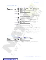
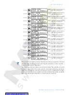
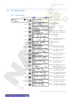
UNDERFREQUENCY
PICKUP: Not Enabled
Range: Not Enabled, Inactive, Timing Out,
Active Alarm, Latched Alarm.
MESSAGE
OVERFREQUENCY
PICKUP: Not Enabled
Range: Not Enabled, Inactive, Timing Out,
Active Alarm, Latched Alarm.
MESSAGE
NEUTRAL O/V (FUND)
PICKUP: Not Enabled
Range: Not Enabled, Inactive, Timing Out,
Active Alarm, Latched Alarm.
MESSAGE
NEUTRAL U/V (3rd)
PICKUP: Not Enabled
Range: Not Enabled, Inactive, Timing Out,
Active Alarm, Latched Alarm.
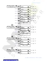
MESSAGE
REACTIVE POWER
PICKUP: Not Enabled
Range: Not Enabled, Inactive, Timing Out,
Active Alarm, Latched Alarm.
MESSAGE
REVERSE POWER
PICKUP: Not Enabled
Range: Not Enabled, Inactive, Timing Out,
Active Alarm, Latched Alarm.
MESSAGE
LOW FORWARD POWER
PICKUP: Not Enabled
Range: Not Enabled, Inactive, Timing Out,
Active Alarm, Latched Alarm.
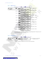
MESSAGE
RTD #1
PICKUP: Not Enabled
Range: Not Enabled, Inactive, Timing Out,
Active Alarm, Latched Alarm.
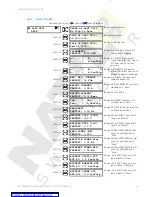
MESSAGE
RTD #2
PICKUP: Not Enabled
Range: Not Enabled, Inactive, Timing Out,
Active Alarm, Latched Alarm.
MESSAGE
RTD #3
PICKUP: Not Enabled
Range: Not Enabled, Inactive, Timing Out,
Active Alarm, Latched Alarm.
MESSAGE
RTD #4
PICKUP: Not Enabled
Range: Not Enabled, Inactive, Timing Out,
Active Alarm, Latched Alarm.
MESSAGE
RTD #5
PICKUP: Not Enabled
Range: Not Enabled, Inactive, Timing Out,
Active Alarm, Latched Alarm.
MESSAGE
RTD #6
PICKUP: Not Enabled
Range: Not Enabled, Inactive, Timing Out,
Active Alarm, Latched Alarm.
MESSAGE
RTD #7
PICKUP: Not Enabled
Range: Not Enabled, Inactive, Timing Out,
Active Alarm, Latched Alarm.
MESSAGE
RTD #8
PICKUP: Not Enabled
Range: Not Enabled, Inactive, Timing Out,
Active Alarm, Latched Alarm.
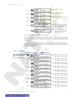
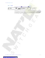
MESSAGE
RTD #9
PICKUP: Not Enabled
Range: Not Enabled, Inactive, Timing Out,
Active Alarm, Latched Alarm.
MESSAGE
RTD #10
PICKUP: Not Enabled
Range: Not Enabled, Inactive, Timing Out,
Active Alarm, Latched Alarm.
MESSAGE
RTD #11
PICKUP: Not Enabled
Range: Not Enabled, Inactive, Timing Out,
Active Alarm, Latched Alarm.
MESSAGE
RTD #12
PICKUP: Not Enabled
Range: Not Enabled, Inactive, Timing Out,
Active Alarm, Latched Alarm.
MESSAGE
OPEN SENSOR
PICKUP: Not Enabled
Range: Not Enabled, Inactive, Timing Out,
Active Alarm, Latched Alarm.
MESSAGE
SHORT/LOW TEMP
PICKUP: Not Enabled
Range: Not Enabled, Inactive, Timing Out,
Active Alarm, Latched Alarm.
Содержание Multilin 489
Страница 3: ...Courtesy of NationalSwitchgear com ...
Страница 4: ...Courtesy of NationalSwitchgear com ...
Страница 110: ...4 48 489 GENERATOR MANAGEMENT RELAY INSTRUCTION MANUAL CHAPTER 4 INTERFACES Courtesy of NationalSwitchgear com ...
Страница 272: ...7 22 489 GENERATOR MANAGEMENT RELAY INSTRUCTION MANUAL CHAPTER 7 TESTING Courtesy of NationalSwitchgear com ...


