5-192
M60 MOTOR PROTECTION SYSTEM – INSTRUCTION MANUAL
GROUPED ELEMENTS
CHAPTER 5: SETTINGS
5
Many motors have a large time margin between acceleration-time and the stall limit. It is advantageous to detect stalling
during a start as early as possible to minimize re-starting delays once the cause of the stall is remedied, for example
neglecting to release a fan brake.
The acceleration time element compares actual starting time with a pre-determined time setting and operates when it is
exceeded. This element has the functionality to adapt the tripping time for starts with lower starting current, and it stores
acceleration time and current of the last five starts. The element uses currents configured under
SYSTEM SETUP
MOTOR
MOTOR LINE SOURCE
and motor status asserted by the thermal model element. Both the signal source and thermal
protection must be configured properly in order for the acceleration time protection to operate.
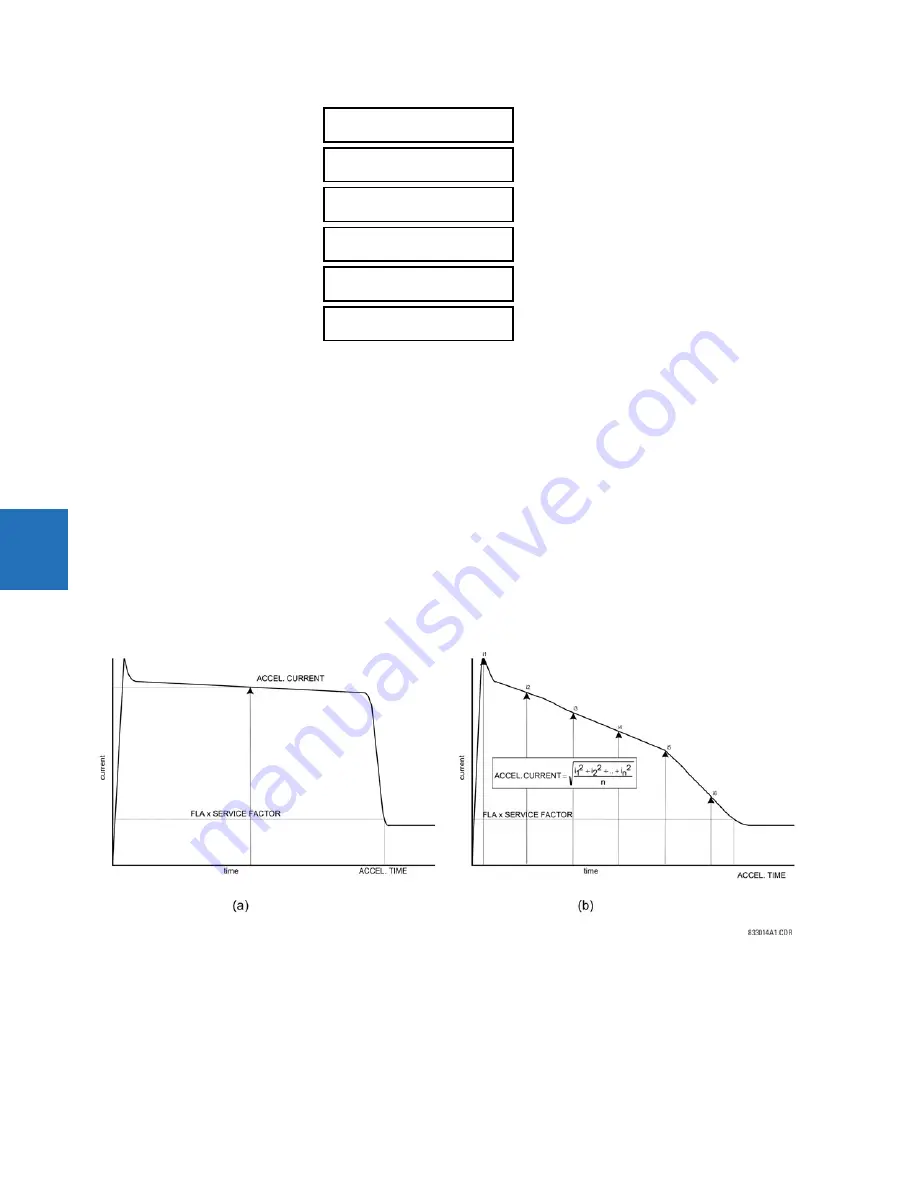
The following figure shows examples of constant and variable acceleration currents and explains measurement of the
acceleration time and current. Part A represents a constant current start, and part B represents a variable current start.
The element stores the basic statistics for the last five successful starts. The following values are retained, available for
display, and accessible via communications: date and time of starting; acceleration time (in seconds); effective
acceleration current (in multiplies of FLC); and peak acceleration current (in multiplies of FLC). Recorded effective
acceleration current and time can be used to fine-tune the relay settings.
Figure 5-98: Sample acceleration currents
ACCELERATION CURRENT
— This setting is only used in the Adaptive mode. It defines a constant current that accelerates the
motor within the normal acceleration time. The setting is used to adapt the tripping action when the current is changing
significantly during the start, such as due to voltage dips.
ACCELERATION TIME
— This setting specifies the maximum acceleration time. If the motor is not in the running state when
this time expires, the element operates. This setting can be estimated experimentally by starting a given motor several
times under various load and electrical conditions and measuring the starting time. Also apply a security margin.
ACCELERATION
CURRENT: 6.00 x FLC
Range: 1.00 to 10.00 x FLC in steps of 0.01
ACCELERATION TIME:
10.00 s
Range: 0.50 to 180.00 s in steps of 0.01
ACCELERATION MODE:
Definite Time
Range: Definite Time, Adaptive
ACCELERATION BLOCK:
Off
Range: FlexLogic operand
ACCLERATION TARGET:
Self-reset
Range: Self-reset, Latched, Disabled
ACCLERATION EVENTS:
Disabled
Range: Disabled, Enabled
Содержание M60
Страница 9: ...TABLE OF CONTENTS M60 MOTOR PROTECTION SYSTEM INSTRUCTION MANUAL ix INDEX ...
Страница 10: ...x M60 MOTOR PROTECTION SYSTEM INSTRUCTION MANUAL TABLE OF CONTENTS ...
Страница 14: ...1 4 M60 MOTOR PROTECTION SYSTEM INSTRUCTION MANUAL FOR FURTHER ASSISTANCE CHAPTER 1 INTRODUCTION 1 ...
Страница 208: ...4 88 M60 MOTOR PROTECTION SYSTEM INSTRUCTION MANUAL FLEXLOGIC DESIGN USING ENGINEER CHAPTER 4 INTERFACES 4 ...
Страница 494: ...5 286 M60 MOTOR PROTECTION SYSTEM INSTRUCTION MANUAL CONTROL ELEMENTS CHAPTER 5 SETTINGS 5 Figure 5 158 Time out mode ...
Страница 552: ...5 344 M60 MOTOR PROTECTION SYSTEM INSTRUCTION MANUAL TESTING CHAPTER 5 SETTINGS 5 ...
Страница 596: ...7 14 M60 MOTOR PROTECTION SYSTEM INSTRUCTION MANUAL TARGETS MENU CHAPTER 7 COMMANDS AND TARGETS 7 ...
Страница 602: ...9 4 M60 MOTOR PROTECTION SYSTEM INSTRUCTION MANUAL SATURATION DETECTOR CHAPTER 9 THEORY OF OPERATION 9 ...
Страница 652: ...C 6 M60 MOTOR PROTECTION SYSTEM INSTRUCTION MANUAL COMMAND LINE INTERFACE APPENDIX C COMMAND LINE INTERFACE C ...
Страница 660: ...iv M60 MOTOR PROTECTION SYSTEM INSTRUCTION MANUAL ABBREVIATIONS ...


