3-6
GE MEDICAL SYSTEMS
ULTRASOUND QUALITY ASSURANCE REFERENCE MANUAL
REV 1
2262684-100
3-7
Isolated Patient Lead (Source) Leakage–Lead to Lead
Reference the procedure in the IEC 601-1.1.
When using the Dale 600, switch the meter’s function selector to the LEAD-LEAD position. See Illustration
3-7. Select and test each of the five ECG lead positions (except ALL) on the LEAD selector, testing each
to the power condition combinations found in the table. Record the highest leakage current measured onto
the appropriate form.
3-7-1
Dale 600 Patient Lead Tests
NEUTRAL POLARITY
1. Closed Normal
2. Open Normal
3. Closed Reversed
4. Open Reversed
3-8
Isolated Patient Lead (Sink) Leakage-Isolation Test
Reference the procedure in the IEC 601-1.1.
When using the Dale 600, switch the meter’s function selector to the LEAD-ISO. Select the ALL position
on the lead selector. Depress the rocker switch to ISO TEST to test lead isolation.
CAUTION
Line voltage is applied to the ECG leads during this test. To avoid possible electric
shock hazard, the system being tested must not be touched by patients, users or
anyone while the ISO TEST switch is depressed.
NOTE:
It is not necessary to test each lead individually or power condition combinations
as required in previous tests.
3-9
Transducer Source Leakage-Isolation Test
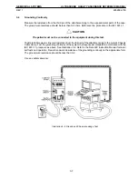
The Dale 600 provides a method for testing probes independently from the system. The meter utilizes a
probe adapter to apply a test potential commonly to all connector pins. See Illustration 3-8.
The probe’s imaging area is immersed in a saline solution
along with a grounding probe from the meter
to complete the current path. Saline solution is a mixture of water and salt. The salt adds a free ion to the
water, making it conductive. Normal saline solution is 0.9% salt or 1/2 gram salt per 1 liter of water. If saline
is not available, a mixture of 1 quart water with one or more grams of table salt, mixed thoroughly, will
substitute.
To test a probe, set the meter’s function selector to EXTERNAL. Connect the probe for test with the meter’s
appropriate adapter. Plug the saline probe into the meter’s connector marked CHASSIS and the probe
adapter into the connector marked EXTERNAL. Add the meter’s saline probe and the imaging area of the
probe into the saline bath. Depress the ISO TEST rocker switch and record the leakage current measured
on the appropriate form.
NOTE:
Each probe will have some amount of leakage, dependent on its design. Small
variations in probe leakage currents are normal from probe to probe. Other variations will
result from differences in line voltage and test lead placement. The maximum allowable
leakage current for body surface contact probe differs from inter-cavity probe. Be sure to
enter the correct probe type in the appropriate space on the check list.
Содержание LOGIQ 200
Страница 4: ......
Страница 8: ......
Страница 10: ...05 23 00 MAC Page 2 of 2 ...
Страница 28: ...05 23 00 MAC Page 2 of 2 ...
Страница 87: ...LOGIQ α200 ...
Страница 88: ...LOGIQ 200 PRO ...
Страница 144: ......
Страница 168: ...GE MEDICAL SYSTEMS LOGIQ 200 PRO Series PROPRIETARY MANUAL 2242594 DIAGNOSTICS 2 31 B MODE CINE TEST ILLUSTRATION 2 15 ...
Страница 190: ......
Страница 196: ......


