background image

Chapter 1. Programming Site Data

10

DigitalFlow™ GF868 Programming Manual (2-Channel)

1.6.1a Procedure Options

After completing the above steps, the meter returns to the 

Channel PROGRAM


prompt. Continue as follows:

To continue programming the meter, refer to the menu maps in Appendix A and navigate to the desired menu. 
Then, proceed to the appropriate section of this manual for instructions.

To leave the 

User Program 

and retain the previous settings, press 

[EXIT]

 twice and then press 

[F1] = NO

 at the


SAVE


prompt. Any programming changes will be discarded and you will be returned to the data display.

To leave the 

User Program

 and return to measurement mode, press 

[EXIT]

 twice and then press 

[F2] = YES

 at the 

SAVE


prompt. Your programming changes will be entered into the meter’s memory, and you will be returned to 

the data display.

Note:

See the 

SAVE

 submenu section on page 37 of this chapter for more information on this function.

1.6.2 Entering System Data for a Channel

Refer to Figure 11 on page 87.

1.

To enter the 

Channel PROGRAM 

menu, press 

[F1] or [F2] 

(depending on the desired channel) at the

 User PROGRAM 

prompt.

2.

To program the 

SYSTM

 submenu, press 

[F2]

 at the 

Channel PROGRAM

 prompt.

IMPORTANT:

Do not confuse this 

SYSTM

 submenu, which is used to enter channel-specific information, with the 

SYSTM


submenu of the 

GLOBL

 menu, which is used to enter information applicable to both channels.

3.

Enter a 

Channel Label

 of up to 9 characters. Press 

[ENT]

.

4.

Enter a 

Channel Message

 of up to 21 characters. Press 

[ENT]

.

5.

Use the [



 and 

[F1]-[F4]

 keys to select the 

Volumetric Units

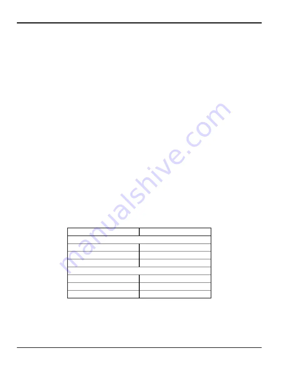
 for the data display, as shown in Table 2.

Table 2: Available Volumetric/Totalizer Units

English

Metric

Actual Units

ACF = Actual Cubic Feet

ACM = Actual Cubic Meters

KACF = Thousands of ACF

KACM = Thousands of ACM

MMACF = Millions of ACF

MMACM = Millions of ACM

Standard Units

SCF = Standard Cubic Feet

SCM = Standard Cubic Meters

KSCF = Thousands of SCF

KSCM = Thousands of SCM

MMSCF = Millions of SCF

MMSCM = Millions of SCM

Содержание DigitalFlow GF868

Страница 1: ...GE Measurement Control Gas Analysis 910 194P2 Rev F February 2015 DigitalFlow GF868 Ultrasonic Flowmeter for Flare Gas Programming Manual 2 Channel ...

Страница 2: ......

Страница 3: ...m 2015 General Electric Company All rights reserved Technical content subject to change without notice DigitalFlow GF868 Ultrasonic Flowmeter for Flare Gas Programming Manual 2 Channel 910 194P2 Rev F February 2015 ...

Страница 4: ...ii no content intended for this page ...

Страница 5: ...us situation which can result in minor or moderate injury to personnel or damage to the equipment if it is not avoided HIGH VOLTAGE This symbol indicates the presence of high voltage It calls your attention to situations or operations that could be dangerous to you and other persons operating the equipment Read these messages and follow the instructions carefully WARNING It is the responsibility o...

Страница 6: ...ic Equipment WEEE take back initiative directive 2012 19 EU The equipment that you bought has required the extraction and use of natural resources for its production It may contain hazardous substances that could impact health and the environment In order to avoid the dissemination of those substances in our environment and to diminish the pressure on the natural resources we encourage you to use ...

Страница 7: ... Outputs 14 1 6 5 Entering Setup Data 16 1 7 Entering Global Data 22 1 7 1 Setting the Clock 23 1 7 2 Entering Global System Data 24 1 7 3 Setting Up Global Inputs Outputs 26 1 7 4 Setting Up Communications 31 1 7 5 MODBUS Register Map 32 1 7 6 Activating Security 35 1 8 Saving Site Files 37 1 9 Recalling Site Files 38 Chapter 2 Displaying Data 2 1 Introduction 39 2 2 The BIG Submenu 40 2 3 The DU...

Страница 8: ...56 3 4 Stopping a Log 57 3 5 Creating an ERROR Log 58 3 5 1 Log Type 59 3 5 2 STARTTIME Prompt 59 3 5 1 START DATE Prompt 60 Chapter 4 Printing Data 4 1 Introduction 61 4 2 Print Live Data 62 4 2 1 Numeric Format 62 4 2 2 Graphical Format 63 4 3 Printing Logs 65 4 3 1 Numeric Format 65 4 3 2 Graphical Format 66 4 4 Print Site File 67 4 5 Stop Printing 68 4 6 Setting Up a Printer 68 4 7 Printing Si...

Страница 9: ...Setup Data 96 Appendix C Programming with PanaView C 1 Introduction 99 C 2 Wiring the RS232 Interface 99 C 3 Setting Up the Communications Port 100 C 3 1 Setting up Ethernet Communications 102 C 4 Adding the GF868 103 C 5 Editing Meter Properties 105 C 5 1 Setting the Meter Clock 107 C 5 2 Reading Transducer Signals 108 C 5 3 Plotting Transducer Signals 109 C 5 4 Saving Transducer Signals 109 C 5 ...

Страница 10: ...Contents viii DigitalFlow GF868 Programming Manual 2 Channel no content intended for this page ...

Страница 11: ...r each submenu are presented in this chapter Refer to the appropriate section for a discussion of the following User Program submenus CH1 CH2 use this submenu to activate a channel and to enter the basic setup parameters for that channel GLOBL use this submenu to enter global meter parameters i e clock system input output communications and security which apply to both channels SAVE use this subme...

Страница 12: ...description of both the unshifted and shifted functions for each of the 39 keys is listed in Table 1 on page 3 Note Only the SHIFT key and the eight Fx keys have no shifted function Figure 1 Model GF868 Keypad Note Although the keypad is essentially the same the front panel layout of meters supplied in one of the optional enclosures is different See Appendix C Optional Enclosures of the Startup Gu...

Страница 13: ...Shift Key use this red key to access the shifted function of the other keys One press shifts the next keystroke only while two presses locks the keypad in shifted mode A third press releases the shift function None Arrow Keys in measurement mode use to scroll through function choices on the option bar In program ming mode use to scroll through menu choices The also acts as a backspace key in progr...

Страница 14: ...y use to confirm the most recent input infor mation Use to enter the letter K Help Key use to access the Model GF868 s context sensitive on line help system See the next section for details Use to enter the letter I Screen Key press the left side to select the left display pane or press the right side to select the right display pane Press the left side to enter the letter V or press the right sid...

Страница 15: ...to enter the letter G Audio Level Key press to increase the audio alarm volume Press to decrease the audio alarm volume Stopwatch Timer Key press to turn the stopwatch timer on Press to turn the stopwatch timer off Backlight Key press to turn the display backlight on or to increase its brightness Press to turn the display backlight off or to decrease its brightness Contrast Key press to increase t...

Страница 16: ... access this function and the next screen of text is displayed in the prompt area EXIT Press F2 or F6 to access this function and the Model GF868 returns to measurement mode ERROR Press F3 or F7 to access this function and the various Model GF868 error codes are displayed Use the F1 F4 or F5 F8 function keys in conjunction with the and keys to obtain additional information on the desired error cod...

Страница 17: ...h totalizer Press the key once in shifted mode to stop the stopwatch totalizer Note Instructions on properly setting up the stopwatch totalizer are given later in this chapter Also the Service Manual provides information on the error response of the stopwatch totalizer 1 4 3 Display Brightness Use the third console control key to adjust the display backlight Discrete presses of this key will incre...

Страница 18: ...e flow rate data Therefore be sure to complete at least the sections of this chapter pertaining to those three submenus Note Because it is so essential instructions for programming the ACTIV SYSTM and PIPE submenus are also included in the Startup Guide If that programming has already been completed skip the corresponding sections of this chapter Except for the three submenus noted above it is not...

Страница 19: ... The meter will exit the ACTIV submenu and return to the channel menu screen As indicated in the above prompt the Model GF868 flowmeter can take measurements in two different ways Skan is the preferred technique for locating the acoustic signal and for high velocity measurements It is more robust in a noisy environment than the Measure technique Measure is the preferred technique to use for making...

Страница 20: ...hapter for more information on this function 1 6 2 Entering System Data for a Channel Refer to Figure 11 on page 87 1 To enter the Channel PROGRAM menu press F1 or F2 depending on the desired channel at the User PROGRAM prompt 2 To program the SYSTM submenu press F2 at the Channel PROGRAM prompt IMPORTANT Do not confuse this SYSTM submenu which is used to enter channel specific information with th...

Страница 21: ...ay 13 Use the F1 F4 to select the Mass Totalizer for the data display 14 Use the F1 F4 to select the Mass Decimal Digits for the data display 1 6 2a Procedure Options After completing the above steps the meter returns to the Channel PROGRAM prompt Continue as follows To continue programming the meter refer to the menu maps in Appendix A and navigate to the desired menu Then proceed to the appropri...

Страница 22: ...ransmit an excitation voltage at the transducer s natural frequency without this data c Enter the special transducer Time Delay Tw value supplied by the factory Press ENT The meter will only accept values from 0 to 1000 sec Note Tw is the time required for the transducer signal to travel through the transducer and its cable This time delay must be subtracted from the transit times of the upstream ...

Страница 23: ... to turn Reynolds Correction off or F2 to turn it on Note Reynolds Correction is a number based on the Kinematic Viscosity and flow rate of the fluid It should be enabled for most applications a When you enable the Reynolds Correction Factor you must also enter the Kinematic Viscosity of your gas as listed in Sound Speeds and Pipe Size Data Use the numeric keys to enter a value and press ENT 1 6 3...

Страница 24: ...ave selected Standard as the equation type in the SYSTM submenu as shown on page 10 4 At the Temperature Input prompt press F1 to enter a constant temperature value or press Fx to select the option card in Slot x that will supply the live temperature input Note Each slot that contains an option card with an analog input assigned to TEMP or an RTD input will appear on the option bar If the process ...

Страница 25: ...INPUT the card may not have been initialized or it may be defective Call the factory for assistance 8 At the N2 Input prompt press F1 to enter a constant nitrogen N2 percentage or press Fx to select the option card in Slot X that will supply the live N2 percentage 9 Do one of the following If you selected FIXED enter the known fixed N2 value Press ENT The meter accepts values from 0 100 If you sel...

Страница 26: ...o enter the signal parameters 1 Press and F1 SIGNL to enter the SIGNAL submenu 2 Press ENT to accept the current Signal Low Limit value or enter a new value and press ENT The meter will only accept values from 20 to 100 The default value for this parameter is 20 The E1 LOW SIGNAL error message appears when the signal strength falls below the programmed SIGNAL LOW LIMIT value Note See the Service M...

Страница 27: ...is 14 and values from 0 to 100 are acceptable The E5 AMPLITUDE error message appears when the amplitude discriminator falls below the programmed AMP DISCRIM LOW value 8 Press ENT to accept the current Amp Discrim High value or enter a new value and press ENT The amplitude discriminator measures the size of the transducer signal received by the Model GF868 The default value for this parameter is 34...

Страница 28: ... accept the current shifts value or enter a new value and press ENT The number of shifts corresponds to the actual number of transmits per cycle number of signals added together in one direction to produce an averaged signal for one interrogation of the fluid and need only be changed if the environment is very noisy or the acoustic signal is weak The default value for this parameter is 3 and value...

Страница 29: ...th based on the expected arrival of the signal After completing these steps the program returns to the SETUP window Table 5 Default Values and Limits for SETUP Parameters Parameter Default Value Low Limit High Limit Signal Low Limit 20 20 100 Cor Peak Limit 100 0 500 Velocity Low Limit 300 0 ft sec 85 m sec 500 ft sec 150 m sec 500 ft sec 150 m sec Velocity High Limit 300 0 ft sec 85 m sec 500 ft ...

Страница 30: ...w and High Limits Acceleration Limit Amplitude Discrimination Low Amplitude Discrimination High Delta T Offset Skan T Offset of Peak and XMIT Sample Size They do not include M S_Switch Shifts A Divisor Transmit Pulses T WINDOW and R WINDOW which remain at their last programmed values 1 Press and F3 INIT 2 Press F1 NO to keep the current values or press F2 YES to reset all values to their default s...

Страница 31: ...T The meter will only accept values from 2 to 20 IMPORTANT When editing the K factor table the velocities must be entered in increasing order d Enter the Velocity Value for K factor number x Press ENT The meter will only accept values from 30 000 to 30 000 ft sec e Enter the K factor corresponding to velocity number x Press ENT 3 Repeat steps c and d until all of the data points have been entered ...

Страница 32: ...M submenus is overridden The following submenus are included in the GLOBL menu CLOCK used to enter the current date and time SYSTM used to specify the units of measure used in calculations I O used to set up error handling and to configure analog inputs and outputs COMM used to set up the serial communications port SECUR used to specify a programming access password After selecting F3 GLOBL at the...

Страница 33: ... 99 b Use the and F1 F4 keys to select the current month c Enter the current day and press ENT The allowable range is 1 to the number of days in the current month 1 7 1b Setting the Time 2 The next prompt displays the programmed Time If the displayed time is correct press F1 OK to return to the GLOBL prompt If the displayed time is incorrect press F2 EDIT to change the time and complete the steps ...

Страница 34: ...r the value and press ENT 3 At the Stopwatch Totalizer prompt press F1 AUTO to measure totals automatically or press F2 MNUAL to measure totals manually with the Stopwatch Timer If AUTO is selected above the meter automatically begins totalizing upon leaving the User Program If MNUAL is selected the console key on the keypad may then be used to start and stop the totalizer The manner in which the ...

Страница 35: ...ys to select the desired number of MDOT Decimal Digits in the mass flow rate display 12 Use the F1 F4 keys to select the desired units for the Mass Totalizer 13 Use the F1 F4 keys to select the number of Mass Decimal Digits in the totalized mass flow display After completing the above steps the program returns to the GLOBL window 1 7 2c Procedure Options After completing the above steps the meter ...

Страница 36: ... if you want the GF868 to Hold the last good reading and continue to totalize based on that reading or press F2 No Up if you want the meter to stop totalizing 3 Press F1 NO to disable 2 path error handling or press F2 YES to enable 2 path error handling For the AVE mode the 2 path error handling option is intended for applications where two sets of transducers are installed in the same location in...

Страница 37: ... an option card will appear on the option bar Refer to the menu map in Figure 14 on page 90 in Appendix A Menu Maps and complete the following steps to setup and or scale the Model GF868 s analog inputs and outputs Slot X Analog Outputs 1 Use the F1 F2 keys to set up outputs A or B respectively Note The set up of output A is used as an example Identical procedures would be used to set up Output B ...

Страница 38: ... to set up another alarm or press EXIT to select another slot for set up 1 7 3c Totalizer Frequency Outputs 1 Press F1 F4 to set up outputs A B C or D respectively 2 Press F1 OFF to disable output A and return to the previous prompt or press F2 FREQ or F3 TTLZR to designate output A as a frequency or a totalizer output respectively Note The setup of output A is used as an example Identical procedu...

Страница 39: ...ency output or press EXIT to select another slot for setup Analog Inputs 1 Press F1 to set up input A or F2 to set up input B Note The set up of input A is used as an example in this manual Identical procedures would be used to set up input B An analog input option card may contain one standard analog input and one RTD analog input 2 Enter a Label of up to eight characters for input A and press EN...

Страница 40: ...F1 F2 to set up another input or press EXIT to select another slot for set up For instructions on setting up additional inputs and or outputs proceed to the appropriate section Otherwise press EXIT twice to return to the Global PROGRAM prompt Procedure Options After completing the above steps the meter returns to the Global I O prompt Continue as follows To continue programming the meter refer to ...

Страница 41: ... keys to select the number of UART Bits 3 Enter a Network ID number between 1 and 254 and press ENT The default number is 1 A network ID number is only necessary for communication with the GE Instrument Data Manager or PanaView software See the software User s Manual for more information IMPORTANT If the network ID number is changed communication with the Instrument Data Manager or PanaView must b...

Страница 42: ...mitter can send flow data and diagnostic information to a flow computer or SCADA serially using a Gould type RTU protocol In this case only the MODBUS function command 3 read multiple registers 6 write multiple registers is valid The format for the data exchange is as follows The send command initiated by the host flow computer or controller comes in the form time delimiter Addr 3 First Register M...

Страница 43: ...t Digits 0 2 21 28 Ch1 Timer 2 4 2 16 bit int 23 2C Ch1 Error Code 0 2 24 2E Ch1 Sound Speed 3 4 2 16 bit int 26 32 Ch1 Molecular Weight 4 4 2 16 bit int 28 36 Ch1 Sig Strength Upstream 1 4 2 16 bit int 30 3A Ch1 Sig Strength Downstream 1 4 2 16 bit int 32 3E Ch1 Temperature 2 4 2 16 bit int 34 42 Ch1 Pressure 3 4 2 16 bit int 36 46 Ch2 Velocity 2 4 2 16 bit int 38 4A Ch2 Act Volumetric Q DIGITS 4...

Страница 44: ...90 Avg Std Volumetric Q DIGITS 4 IEEE 32 bit 75 94 Avg Fwd Totals T DIGITS 4 2 16 bit int 77 98 Avg Rev Totals T DIGITS 4 2 16 bit int 79 9C Avg Tot Digits 0 2 80 9E Avg Mass Flow M DIGITS 4 IEEE 32 bit 82 A2 Avg Fwd Mass Totals MT DIGITS 4 2 16 bit int 84 A6 Avg Rev Mass Totals MT DIGITS 4 2 16 bit int 86 AA Avg Mass Tot Digits 0 2 87 AC Avg Timer 2 4 2 16 bit int 89 B0 5Avg Error Code 0 2 90 B2 ...

Страница 45: ...ing with the flowmeter s programming the Model GF868 is equipped with a security feature that locks out the following menus Program Menu PROG Calibration Menu CAL Log Menu LOG Clear Menu CLR When the system is locked access to the above menus will be denied unless the correct password is entered The Model GF868 is shipped with a default password which is given later in this section For increased s...

Страница 46: ...p in mind that the password may have to be entered frequently from the keypad A long and or complex password may soon become annoying to use 5 Verify the New Password by entering it again and press ENT Be sure to record the new password in a safe place 1 7 6a Procedure Options After completing the above steps the meter returns to the Global PROGRAM prompt Continue as follows To continue programmin...

Страница 47: ... memory an existing site file must be deleted before a new site file name can be assigned See Chapter 5 Clearing Data for details When a site file is stored in memory it becomes the active site file until another site file is created or retrieved See the next section for instructions on retrieving a site file To verify that the site file has been saved use the key to scroll back to the SITE NAME p...

Страница 48: ...files The files are listed in chronological order by creation date Upon recall the selected site file becomes active and all of its programmed parameters become current IMPORTANT The CLOCK and I O data is not recalled with the site file while the SYSTM and COMM data is recalled with the site file Note If you have loaded a site file into a GF868 but the option cards are not in the same slots or pro...

Страница 49: ...IG displays a single measurement in large size text DUAL permits the simultaneous display of two measurements in the same screen pane in standard size text GRAPH displays a graph of either velocity or volumetric flow versus time LOG displays the data stored in a log file either graphically or numerically SIGNL graphically displays any one of five transducer signals versus time BACKL sets the time ...

Страница 50: ...f a different display mode is active access the Display Menu by pressing the DISP key Velocity Ft s 6 95 error codes appear here VEL VOLUM TOTL TOTL DISPLAY FEATURES Press F1 to select the BIG option The measurement mode screen reappears with the display in the BIG format DISPLAY FORMAT previous selection appears here BIG DUAL GRAPH LOG site label site file Use the F1 F4 and keys to select the des...

Страница 51: ...that parameter The parameter previously displayed at the top of the display is moved to the bottom of the display and the previous bottom parameter is no longer shown 2 4 The GRAPH Submenu The GRAPH submenu permits the display of either the flow velocity mass flow or the volumetric flow on an XY bar graph with a specified time interval on the x axis This section describes the procedures for settin...

Страница 52: ... the seconds Because the times displayed in the GRAPH format are in whole minutes only movement of the cursor may not result in a visible change in the posted times For example if a TIME INCREMENT of 30 seconds has been programmed two presses of either cursor movement key will be required to change the displayed time by one minute 1 23 Ft s 10 16 Use the and F1 F4 keys to select the desired option...

Страница 53: ...mpt the option bar will show the names of all log files that are currently stored in memory If there are no log files currently stored in memory the following prompt will appear instead If the All Logs Cleared prompt appears at least one log file must be created and stored in memory before the Display Log function can be accessed See Chapter 3 Logging Data for instructions on creating a log file A...

Страница 54: ... number The first line of the prompt area shows the time and date that the record was created and the next three lines list the values for the three logged parameters Finally any error condition that existed at the time the record was taken is indicated by an error code in the bottom line of the prompt area PAGE 1 REC 80 Use the and F1 F4 keys to view additional records or to exit the log display ...

Страница 55: ...ata for details on creating a log file 1 23 Ft s 10 16 Use the and F1 F4 keys to select the desired option The options are listed in Table 12 V E L ST 08 MAR 09 50 CURS CURS START END Table 12 Graphical Log Display Options Option Bar Choice Description F1 CURS Move the cursor one record to the left and display the value and time of that record in the status line i e 6 85 Ft s 10 38 F2 CURS Move th...

Страница 56: ...her cursor movement key will be required to change the displayed time by one minute 2 6 Displaying the Transducer Signal The SIGNL submenu permits the direct graphical display of several transducer signals Specifically the signals listed in Table 13 may be viewed in this format Note The Measure type signals Mup and Mdown are available only if the S M burst technique was selected in the ACTIV menu ...

Страница 57: ...surement at the current cursor location However there is still an inverse video pointer at the far right of this line to indicate that additional option bar choices are available 107 686 798mi Use the and F1 F4 keys to select the desired option The options are listed in Table 14 S U P ST 594 298usec CURS CURS PAGE PAGE Table 14 Graphical Log Display Options Option Bar Choice Description F1 CURS Mo...

Страница 58: ... key doubles the height of the graph while each press of the 5 key halves the height of the graph The three available scale factors are 1x 2x and 4x Horizontal Scaling The 7 and 8 keys are used to scale the graph horizontally Each press of the 7 key doubles the T INC value 2x horizontal compression while each press of the 8 key halves the T INC value 2x horizontal expansion The four available comp...

Страница 59: ...y be turned off At the next keypad entry the backlight will be turned on and the specified time out interval will begin again 2 8 Activating Sleep Mode During times when the display is not in use use the SLEEP submenu to temporarily suspend LCD display activity which allows the Model GF868 to process data more quickly Press the appropriate side of the SCREEN key to activate the desired pane of the...

Страница 60: ...Chapter 2 Displaying Data 50 DigitalFlow GF868 Programming Manual 2 Channel no content intended for this page ...

Страница 61: ...cords for data logging Each page is assigned a header to distinguish one page from another The header contains the log title start date and time end date and time and the time increment Each record contains the date and time of the measurement and the values for the three logged parameters Note Each log file uses at least one page of memory and the same page can not be shared by two different logs...

Страница 62: ...og file Note At the NAME prompt the option bar will show the names of all completed or active log files that are currently stored in memory Recall that a flashing asterisk appears at the far right of the locator bar if the Model GF868 is currently logging data see Chapter 3 Operation of the Startup Guide 4 At the Log Message prompt enter a brief description up to 21 characters of the log Press ENT...

Страница 63: ... circular log automatically stops when the meter runs out of memory or the specified END TIME is reached A circular log runs continuously until manually stopped but only the data from the most recent log cycle is saved At the start of each cycle the oldest recorded data is overwritten by the new data from the current cycle 3 2 2 STARTTIME Prompt 10 Press F1 to accept the displayed start time or pr...

Страница 64: ...elected complete the steps on the next page Note The log END TIME must exceed the log START TIME by at least five minutes Failure to observe this restriction will result in an error message a Press F1 F2 to select AM or PM Then enter the desired Hour 1 12 and press ENT Entry of a start time earlier than the current time will generate an error message b Enter the desired Minutes and press ENT The a...

Страница 65: ...min 30min and 60 min The time increment is the frequency at which the Model GF868 takes and records data measurements If any reading takes longer than the programmed time increment the log is filled in with the next consecutive reading For example assume that a velocity value of 3 ft sec is recorded at 12 00 00 in a log with a time increment of five seconds If the next reading is 8 ft sec and it t...

Страница 66: ...y all currently programmed logs is given If the number of pending pages exceeds the number of free pages additional memory may be made available by clearing some old logs see Chapter 5 Clearing Data If it is undesirable to delete old logs to free up additional memory the number of pages pending may be reduced by altering the parameters of one or more of the currently active logs For example either...

Страница 67: ...he log remains in memory To clear the log from memory refer to Chapter 5 Clearing Data for instructions 2 Press F3 STOP 3 Use the and F1 F4 keys to select a log file to stop Note At the NAME prompt the option bar will show the names of all completed or active log files that are currently stored in memory Recall that a flashing asterisk appears at the far right of the locator bar if the Model GF868...

Страница 68: ...for details enter the assigned password and press ENT 2 Press F4 ERROR 3 Use the and F1 F4 keys to inspect a completed log or to change an active log or enter a new Name up to 5 characters and press ENT to create a new log file Note The option bar lists all error logs currently stored in memory Recall that a flashing asterisk appears at the far right of the locator bar if the Model GF868 is curren...

Страница 69: ... non circular log automatically stops when the meter runs out of memory or the specified END TIME is reached A circular log runs continuously until manually stopped but only the data from the most recent log cycle is saved At the start of each cycle the oldest recorded data is overwritten by the new data from the current cycle 3 5 2 STARTTIME Prompt 10 Press F1 to accept the displayed start time o...

Страница 70: ...e and F1 F4 keys to select the desired Month c Enter the desired Day and press ENT The acceptable range is 1 to the number of days in the selected month 28 29 30 or 31 3 5 1a Procedure Options You have completed setting up the error log Do one of the following Use and to review the previous menu prompts Press F1 F4 to select one of the LOG submenus To return to the data screen and begin logging da...

Страница 71: ... or graphical format LOG use to print a log file in numeric or graphical format PROG use to print a site file STOP use to terminate any active print jobs PRNTR use to specify the printer currently connected SGNLS use to print transducer signal array data RTDs use to send the numeric point value of a connected RTD device to the RS232 port For purposes of this discussion it is assumed that the left ...

Страница 72: ...elect the DATA option 3 Press F1 NUM to print the data in numeric format or press F2 PLOT to print the data in graphical format If you press F1 go to step 4 If you press F2 go to step 8 4 2 1 Numeric Format 4 Use the and F1 F4 keys to select the first parameter to be printed See Table 18 for a list of the available options Refer to Chapter 3 Diagnostics of the Service Manual for a discussion of th...

Страница 73: ...see the instructions for the STOP submenu A portion of a typical printout is shown in Figure 3 Figure 3 Typical Numeric Printout 4 2 2 Graphical Format To print live data in graphical format continue as follows 8 Use the and F1 F4 keys to select the first parameter to be printed See Table 19 on page 64 for a list of the available options DATA_DUMP OF SITE NAME Ch1 Channel LABEL Channel Message Sta...

Страница 74: ...s are taken The available options are 5sec 10sec 30sec 1min 3min 6min and 12min After the time increment is chosen the Model GF868 returns to the standard data display screen and continues to take measurements The live data is printed at the specified time intervals until a STOP command is issued see the instructions for the STOP submenu A portion of a typical printout is shown in Figure 4 Figure ...

Страница 75: ...tored in memory If an active log is selected for printing only the data already accumulated at the time of the print command will be printed 5 Enter the number of the First Page of the log to print and press ENT This prompt does not appear if the log file is only one page long 6 Enter the total number of log pages to print and press ENT This prompt does not appear if the log file is only one page ...

Страница 76: ...ress F1 to show only the positive Y axis or press F2 to display both the positive and negative y axis The Model GF868 returns to the standard data display screen and begins printing the log file The printout continues until the entire log has been printed or until a STOP command is issued see the instructions for the STOP submenu A portion of a typical printout is shown in Figure 6 Figure 6 Typica...

Страница 77: ...rrently in memory appear on the option bar The active site file is always listed as the first choice Work The Model GF868 returns to the standard data display screen and generates a site file printout similar to the one shown in Figure 7 The printout continues until the entire file has been printed or until a STOP command is issued see the instructions for the STOP submenu on the next page Figure ...

Страница 78: ...menu to specify the type of printer connected to the Model GF868 To set up a printer refer to Figure 16 on page 92 and complete the following steps IMPORTANT A printer must be properly set up before proceeding to any of the other sections in this chapter 1 To access the Print Menu press the PRNT key Note The Print Menu is not protected by the security feature and a password is never required to ac...

Страница 79: ...t the SGNLS submenu 3 Press the F1 F3 keys to select the desired Signal Array data to print To abort the procedure press the EXIT key Note The SIGNL option causes the raw signal array data to print while the CROSS option causes the cross correlation data to print The BOTH option prints both sets of data After the desired print selection has been made the Model GF868 returns to the standard data di...

Страница 80: ...nting RTD Data Use the RTDs submenu to send the numeric point value of a connected RTD device to the RS232 port for display on a terminal or RS232 printer By viewing the point value of the meter at a given temperature you can calculate the points at the Set Temperature and the slope of the RTD input in points degree See Chapter 1 Calibration of the Service Manual for more details 1 To access the P...

Страница 81: ... creating a site file and for setting up the stopwatch totalizer see Chapter 1 Programming Site Data For purposes of this discussion it is assumed that the left pane of the data display screen is active If the right pane of the data display screen is active all of the instructions remain the same except that any references to the F1 F4 keys should be replaced by the F5 F8 keys IMPORTANT None of th...

Страница 82: ...ps 1 To access the Clear Menu press the CLR key a If you have activated the security feature see Chapter 1 Programming Site Data page 35 for details enter the assigned password and press ENT 2 Press F1 TOTAL 3 Press F1 to abort the procedure or press F2 to clear all volumetric totals and reset the stopwatch totalizer In either case the initial Clear Menu prompt returns 5 2 0a Procedure Options Do ...

Страница 83: ...ame prompt use the and F1 F4 keys to select a site file for deletion To leave the SITE submenu press the EXIT key Note At the Site Name prompt the option bar shows the names of all site files currently stored in memory 4 Press F1 to abort the procedure or press F2 to Clear the specified site file If any site files remain in memory the Site Name prompt repeats When all of the stored site files have...

Страница 84: ...word and press ENT 2 Press F3 LOG 3 At the Name prompt the option bar shows the names of all log files currently stored in memory Use the and F1 F4 keys to select a log file for deletion To leave the LOG submenu press the EXIT key 4 Press F1 to abort the procedure or press F2 to Clear the specified log file If any log files remain in memory the Name prompt repeats When all of the stored log files ...

Страница 85: ...Table 21 lists the standard cables available from the factory for this purpose Each of the cables listed in Table 21 is available in several standard lengths However a user supplied cable may be used if preferred In either case wire the GF868 end of the serial cable in accordance with the pin designations listed in Table 22 Note For serial communications between a single GF868 and a single persona...

Страница 86: ...00 and 19200 baud After verifying or changing the baud rate setting press the EXIT key three times to return to standard measurement mode Note Refer to Chapter 1 Programming Site Data for a detailed description of using the COMM Submenu PROGRAM Start Press the F3 key to select the GLOBL menu PROGRAM previous selection appears here CH1 CH2 GLOBL SAVE PROGRAM Start Press the F4 key to select the COM...

Страница 87: ...een Using the Settings Menu select the Communications option 3 When the Communications Screen appears make the following selections Baud Rate set to the same value as the GF868 setting Data Bits 8 Stop Bits 1 Parity None Flow Control Xon Xoff Connector select the correct communications port Parity Check not checked Carrier Detect not checked 4 Using the Transfer Menu select the Receive Text File o...

Страница 88: ...When the COMx PROPERTIES window appears make sure the settings are as follows Bits per Second 9600 must match the GF868 setting Data Bits 8 Parity None Stop Bits 1 Flow Control Xon Xoff After making any necessary changes click on OK 5 Open the TRANSFER menu and select CAPTURE TEXT Enter the desired DRIVE DIRECTORY FILENAME for the file about to be transmitted and click on OK 6 From the keypad on t...

Страница 89: ...witch or circuit breaker The disconnect device must be marked as such clearly visible directly accessible and located within 1 8 m 6 ft of the electronics console 6 5 1 Interface Converter Mounting A special bracket containing the serial interface converter and a three terminal barrier strip is mounted inside the Model GF868 just below the RS232 terminal block see Figure 9 The standard RS232 termi...

Страница 90: ...nal on the barrier strip is the screw opposite the red wire connection and the XMT terminal on the barrier strip is the screw opposite the green wire connection 4 Reinstall the clear plastic shroud close the cover to the electronics console and reconnect the main power The RS485 serial interface is now ready for point to point operation However the installed version of the Model GF868 software mus...

Страница 91: ...a small screwdriver to pry open the plastic case of the serial interface converter as shown in Figure 10 The serial interface converter contains a main printed circuit board and a daughter printed circuit board The daughter board has a small terminal block attached to it and the main board has a DIP switch SW1 mounted near the center of the board 6 Locate the switch assembly on the main board and ...

Страница 92: ...s the last unit in the chain 2 Using a twisted wire pair connect the XMT terminal of the barrier strip to the T R terminal of the PC s RS485 adapter and connect the XMT terminal of the barrier strip to the T R terminal of the PC s RS485 adapter see the documentation provided with the RS485 adapter for details Note The XMT terminal on the barrier strip is the screw opposite the red wire connection ...

Страница 93: ...y connected to the subnet You can identify the GF868 by its MAC address supplied as part of customer documentation The default IP Port is 2101 The default IP addressing for the GF868 is DHCP dynamic If you need to assign a static IP address to the GF868 complete the following steps IMPORTANT To assign a static IP address the GF868 must be connected to an Ethernet network with a dynamic address ass...

Страница 94: ...he subnet You can identify the GF868 by its MAC address supplied as part of customer documentation The default TCP Port is 502 The default IP addressing for the GF868 is DHCP dynamic If you need to assign a static IP address to the GF868 complete the following steps IMPORTANT To assign a static IP address the GF868 must be connected to an Ethernet network with a dynamic address assignment mechanis...

Страница 95: ...DigitalFlow GF868 Programming Manual 2 Channel 85 Appendix A Menu Maps Appendix A Menu Maps ...

Страница 96: ...86 DigitalFlow GF868 Programming Manual 2 Channel no content intended for this page ...

Страница 97: ... F2 1 F1 0 TOTAL DECIMAL DIGITS F4 F1 TONS KG F3 F2 KLB F1 LB F2 MMLB F4 DAY F3 F2 MIN F1 SEC HR F4 3 F3 F2 1 F1 0 2 MASS FLOW TIME MDOT DECIMAL DIGITS F4 F1 TONS KG F3 F2 KLB F1 LB F2 MMLB F4 3 F3 F2 1 F1 0 2 MASS DECIMAL DIGITS MASS TOTALIZER F4 F1 500k 25k F3 F2 100k F1 50k F2 200k FREQUENCY SPECIAL TRANSDUCER Tw 33k F1 SPEC F2 m F1 F2 feet F1 inch mm m PI ft PI in PI mm PI F4 F3 F4 F3 English ...

Страница 98: ...Plain text represents prompt area messages and boxed text represents option bar choices Fx represent function keys to select option bar choices 8 4 2 16 32 Skan T OFFSET M S_Switch SET UP PROGRAM F1 F2 F3 F4 F1 F2 F3 FIXED SLOT1 SLOT2 SLOT3 SLOT4 SLOT5 SLOT6 F1 F2 A B F1 F2 F3 F4 F1 F2 F3 FIXED SLOT1 SLOT2 SLOT3 SLOT4 SLOT5 SLOT6 A LABEL B LABEL FIXED TEMP BASE TEMP PRESSURE INPUT F1 F2 A B A LABE...

Страница 99: ...TONS KG F3 F2 KLB F1 LB F2 MMLB English Metric F4 3 F3 F2 1 F1 0 2 MASS DECIMAL DIGITS MASS TOTALIZER F4 F1 2400 4800 F3 F2 600 F1 300 F2 1200 9600 F4 SITE4 F3 SITE3 F2 SITE2 F1 SITE1 F4 F3 F2 F1 SITE NAME SITE4 SITE3 SITE2 SITE1 English Metric F4 F1 SAVE RECLL F3 F2 CH2 F1 CH1 PROGRAM Global PROGRAM F2 EDIT F1 OK DATE MONTH I O F3 See Figure A 4 YEAR F2 PM F1 AM F2 EDIT F1 OK TIME HOUR MINUTES SE...

Страница 100: ... Analog Outputs F1 A F2 F4 D F3 C B Slot x Output X F1 OFF F2 F3 TTLZR FREQ F1 CH1 F2 F4 DIF F3 SUM CH2 F1 AVE Channel F1 VEL F2 F4 TOTL F3 TOTL VOLUM F1 MDOT F2 F4 DIAG F3 MASS MASS BASE FULL Output measurement Slot x Freq Total Outputs F1 TOTL F2 F4 MASS F3 MASS TOTL FREQ Output measurement TTLZR FULL SCALE FREQUENCY UNITS PULSE Entity to totalize F1 A F2 B F1 OFF F2 F4 SPEC F3 TEMP PRESR Slot x...

Страница 101: ... FORMAT NUMERIC LOG DISPLAY SCREEN GRAPHICAL LOG DISPLAY SCREEN F2 CURS F1 CURS F4 PAGE F3 PAGE F2 END F1 START F3 YMAX F4 T INC F1 EXIT GRAPHICAL DISPLAY SCREEN F2 CURS F1 CURS F4 PAGE F3 PAGE F2 END F1 START F3 YMAX F4 T INC F1 EXIT F1 only F2 GRAPHICAL DISPLAY SCREEN Y AXIS MAX Y RANGE F2 CURS F1 CURS F4 F3 F2 END F1 START F3 YMAX T INC EXIT STANDARD DATA DISPLAY SCREEN Backlight timeout Y AXIS...

Страница 102: ...y F2 TIME INCREMENT Y AXIS MAX Y RANGE F1 F2 NUM PLOT FORMAT NAME log 1 page 1st page pages PLOT option log 1 page NUM option F1 only F2 Y AXIS MAX Y RANGE F4 F1 KODAK SP401 F3 EPSON F2 XTECH F1 DP411 STANDARD DATA DISPLAY SCREEN 1st value printed SGNLS F2 RTDs F3 F2 YES F1 NO F3 BOTH F2 CROSS F1 SIGNL SIGNAL ARRAY Printer Type F4 DIF F3 SUM F2 CH2 F1 CH1 1st value printed F1 AVE F4 TOTL MDOT F3 T...

Страница 103: ... more files if more files F1 F2 NO YES F1 F2 OK EDIT F2 NOW STARTTIME F1 F2 AM PM HOUR F1 F2 OK EDIT F3 TODAY START DATE F1 F4 JAN DEC MONTH MINUTES SECONDS YEAR 12 choices F1 F2 OK EDIT F3 TIMED END TIME F1 F2 AM PM HOUR F1 F2 OK EDIT F3 TODAY END DATE F1 F4 JAN DEC MONTH MINUTES SECONDS YEAR 12 choices F1 F3 10min 24 HR LOG TIME 7 choices DAY F1 F1 5sec 60min TIME INCREMENT 9 choices F1 F2 HOURS...

Страница 104: ...Appendix A Menu Maps DigitalFlow GF868 Programming Manual 2 Channel 94 ...

Страница 105: ...Cards Installed Whenever an option card is installed in one of the Model GF868 s expansion slots record the type of card and any additional setup information in the appropriate row of Table 24 Table 24 Option Cards Installed Slot Type of Option Card Additional Setup Information 0 Analog Outputs A B 1 2 3 4 5 6 ...

Страница 106: ...hannel Label Channel Label Channel Message Channel Message Gas Equation Standard Actual Gas Equation Standard Actual Vol Units Vol Units Vol Time Units Vol Time Units Vol Dec Digits Vol Dec Digits Totalizer Units Totalizer Units Tot Dec Digits Tot Dec Digits Mass Flow Mass Flow Mass Flow Time Mass Flow Time MDOT Dec Dig MDOT Dec Dig Mass TOT Mass TOT Mass Dec Dig Mass Dec Dig System Parameters GLO...

Страница 107: ... Type Air Other Fluid Type Air Other Other Sndspd Other Sndspd Reynolds Corr Off On Reynolds Corr Off On Kin Visc Kin Visc Cal Factor Cal Factor Advanced Features CH1 CH2 SETUP ADVAN Static Density No Yes Static Density No Yes Rho Mw Rho Mw Multi K Factors No Yes Multi K Factors No Yes K Factor Table K Factor Table K Factor Velocity K Factor K Factor Velocity K Factor 1 1 2 2 3 3 4 4 5 5 6 6 7 7 8...

Страница 108: ...98 DigitalFlow GF868 Programming Manual 2 Channel no content intended for this page ...

Страница 109: ...ve graph and log files display text output and graphs of live measurement data create custom templates for displaying text graph and log data interface with multiple GE instruments This document focuses on particular applications suitable for the GF868 For general PanaView applications such as creating graph and log files displaying live measurement data and creating custom templates please refer ...

Страница 110: ...to establish communications with the GF868 1 Open the New Meter Browser window and expand the network tree Then highlight the My Computer Name branch by clicking on it 2 Pull down the Edit menu by clicking on it in the menu bar 3 Click on the New menu option to select it and a submenu opens with two choices on it see Figure 18 Figure 18 Edit Menu ...

Страница 111: ...M Port Type menu and click on the desired type or on TCP IP if the GF868 is using an Ethernet connection Note If you select TCP IP the menu changes Proceed to the next page 7 Select any suitable available baud rate A baud rate of 19 200 is appropriate for almost all applications However if you experience periodic communication reliability problems you may wish to consider lowering the baud rate on...

Страница 112: ...s If the IP address is unknown run the Device Discovery software utility All units found will be identified by their MAC address and the assigned IP address In the Port Number box enter 2101 the default value 3 Click OK to complete data entry IMPORTANT If you are using Ethernet communications be sure the GF868 is set up with the default communications parameters 9600 baud no parity no handshaking ...

Страница 113: ...it and then open the Edit menu on the menu bar if the communication port is not highlighted first the New Meter option is not active in the Edit menu 2 Click on the New option in the Edit menu see Figure 21 Figure 21 New Option in the Edit Menu 3 After clicking on the New option the Meter menu option appears Click on this option to select it 4 The New IDM Meter screen shown in Figure 22 opens Ente...

Страница 114: ...Updated Network Tree Note The model number and version that appear will vary with your particular meter and software version However if the settings do not match or there is some other difficulty a screen appears similar to Figure 24 Figure 24 Communication Error Screen The screen offers the options of trying again or of canceling the operation Click on the desired choice and then on OK to confirm...

Страница 115: ...clock or synchronize it with the PC clock Read plot and save transducer signals Clear totalizers Save site files to the meter or PC Clear sites from the meter Print site files to the PC To edit the properties of your GF868 1 Highlight the meter as shown in Figure 23 on page 104 2 Open the Edit menu and select the Properties option as shown in Figure 25 Figure 25 Properties Option in the Edit Menu ...

Страница 116: ...ction on the following pages Setting the Meter Clock page 107 Reading Transducer Signals page 108 Plotting Transducer Signals page 109 Saving Transducer Signals page 109 Clearing Totalizers page 109 Handling Site Files page 110 Figure 26 Properties Window for IDM Based Meter Note For illustration purposes the meter shown here is a one channel GX868 flowmeter Specific parameters will vary with your...

Страница 117: ...fferent ways manually enter the time and date in the text box or click on the Sync to PC option button to have PanaView set the time and date to the current PC setting or click on the Set option button to open the dialog box shown in Figure 27 Set the desired date and time as indicated and click on the OK option button Figure 27 Time and Date Selection Window ...

Страница 118: ...ls button If the meter is a multi channel instrument open the Channel drop down menu and click on the desired channel After a moment the Properties window appears similar to Figure 28 Figure 28 Active Signal Options in Properties Window 2 To select a different signal type open the signal menu at the right shown here with Raw Upstream highlighted and click on the desired signal ...

Страница 119: ...n in Figure 29 Figure 29 Signal Graph Window C 5 4 Saving Transducer Signals To save the raw signal click Save A window opens similar to Figure 30 Enter the desired name and click Save to save the signal as a text file Figure 30 Save As Window C 5 5 Clearing Totalizers To clear the meter totalizers click on the Clear Totalizers button in the Properties window The meter totalizers are reset to 0 ...

Страница 120: ...shown in Figure 31 opens Figure 31 Site File Operations Window C 5 6a Saving an Existing Site to the Meter To save an existing site to the meter 1 Select the radio button for Selected and highlight an existing site in the left pane 2 Then click on the Save Site to Meter button A screen opens similar to Figure 32 Figure 32 Site File Selection 3 Highlight the desired site and click Open PanaView sen...

Страница 121: ...red settings C 5 6c Saving a Site to the PC To save a site to the PC 1 Highlight the desired site in the left pane See Figure 31 on page 110 2 Click Save Site to PC A window opens similar to Figure 30 on page 109 3 Enter the desired site name and click Save PanaView saves the site in the PanaView folder unless otherwise specified Note If you have created a site on the meter after opening the Site ...

Страница 122: ...ne See Figure 31 on page 110 2 Click Save Site Print to PC 3 The Site File Selection window opens refer to Figure 32 on page 110 Enter the desired site name now with a prt suffix and click Save PanaView displays a text version of the site as shown in Figure 34 Figure 34 Printout of Site File 4 Click Close once to close the Site File Operations window and a second time to close the Properties windo...

Страница 123: ...er They can Program and change a meter s operating parameters Set up start and stop logs Calibrate and test inputs and outputs Clear various files To access meter programming 1 Enter the New Meter Browser option from the File menu 2 Expand the network tree until you reach the desired meter 3 Then expand the meter tree as shown in Figure 35 Figure 35 New Meter Browser with Meter Branch ...

Страница 124: ...er Figure 36 Meter Tree with Edit Functions Option 5 To open a particular menu double click on that menu on the tree For example if you double click on the Site Edit Menu a window opens similar to Figure 37 Figure 37 Site Edit Menu Window Note The options listed in the left pane correspond to the options available in the GX868 PROGRAM menus For more information about the options in your instrument...

Страница 125: ...entry requires a numeric value change the value displayed in the right pane Figure 38 Pipe Parameters Option in Site Edit Menu c Do one of the following Click on Next Item to proceed to the next menu item or Click on Previous Item to return back through the menu to a previous item Note If you click on either Next Item or Previous Item without changing the settings the current settings remain uncha...

Страница 126: ...ent Settings 7 When you have completed entering parameters in a given option click Exit Page to close the option You can then double click on another option or click Close to close the window You can double click on another menu to modify its settings or return to the New Meter Browser For additional PanaView functions refer to the PanaView User s Manual ...

Страница 127: ...Ch2 Mass Flow MASS_U Avg Mass Flow MASS_U Ch1 Fwd Mass Totals MTOT_U Ch2 Fwd Mass Totals MTOT_U Avg Fwd Mass Totals MTOT_U Ch1 Rev Mass Totals MTOT_U Ch2 Rev Mass Totals MTOT_U Avg Rev Mass Totals MTOT_U Ch1 Mass Tot Digits none Ch2 Mass Tot Digits none Avg Mass Tot Digits none Ch1 Timer sec Ch2 Timer sec Avg Timer sec Ch1 Error Code none Ch2 Error Code none Avg Error Code none Ch1 SSUP none Ch2 S...

Страница 128: ...en placed in the OOS out of service mode before executing D 3 Selecting the Desired Measurements To set the measurement unit for each AI 1 Double click on the FLOW Transducer Block in the tree under GEFlow XMT 2 Select the Others tab and open the drop down list for the PRIMARY_SELECTOR and SECONDARY_SELECTOR see Figure 41 on page 119 3 Choose the unit from the list see Figure 41 on page 119 This u...

Страница 129: ... D 3 Selecting the Desired Measurements cont 4 After the desired measurements have been selected for the PRIMARY and SECONDARY SELECTOR choose the unit system UNIT_SELECTOR above the PRIMARY_SELECTOR that has been programmed in the flowmeter English or SI Figure 41 Primary Selector Drop Down List ...

Страница 130: ...ch you wish to set the units ANALOG_INPUT_1 or ANALOG_INPUT_2 in the tree under GEFlow XMT see Figure 40 on page 118 2 Select the Scaling tab and set the unit for the measurement based on the flowmeter settings For example if the flowmeter was set to use the metric unit system and the PRIMARY_SELECTOR was set to use VELOCITY you would choose m s for the unit as shown in Figure 42 Figure 42 Units I...

Страница 131: ...ouble click on the FLOW transducer block in the tree under GEFlow XMT see Figure 40 on page 118 2 Select the Others tab and scroll down to the CLEAR_TOTALIZERS listing 3 Select Clear from the drop down list box see Figure 43 4 After the totals have been reset select Normal from the drop down list box to resume total accumulation Figure 43 Clear Totalizers Drop Down List ...

Страница 132: ...ple setup using the Function Block Application editor The flowmeter AI blocks along with the AO and PID of another device on the network are displayed We have connected the AI_1 OUT of the flowmeter to the CAS IN of the AO block We have also connected the AI_2 OUT of the flowmeter to the CAS IN of the PID block Figure 44 Function Block Application ...

Страница 133: ...quire special programming software to configure a good status on the PV Yes 1 9 Does the Device feature a Non Volatile Memory protection feature If so what are the steps to disable enable from the Resource or Transducer block No 1 10 HOST System registered Yokogawa TBD Emerson Honeywell TBD ABB TBD 1 11 Design Concept Entity Concept 1 12 FISCO Compliant No 1 13 FNICO Compliant Yes models XGM868i X...

Страница 134: ...nimum Voltage 9 VDC 3 41 Device Resistance Ohms fieldbus terminal to 30 Mega Ohms increasing 3 42 Device Resistance Ohms fieldbus terminal to Ground open circuit 20 MOhm 3 43 Device Resistance Ohms fieldbus terminal to Ground open circuit 20 MOhm 3 51 Capacitance microF to 1 pF 3 52 Capacitance microF to Ground 634 7 pF 3 53 Capacitance microF to Ground 635 7 pF 3 6 4 wire Device if so what AC DC ...

Страница 135: ...t version of the FF spec FF 902 FS 1 4 7 2 Block Type Flow Display 7 3 Block Class Std Enhanced Custom Custom Custom Does the Device support Methods in the Resource and Transducer Blocks If it does then the functionality will be tested No 7 4 Special Features besides Methods multiple VIEWS etc Multiple View3s and View4s Device specific advanced diagnostics Yes 8 Function Blocks 8 1 Does the Device...

Страница 136: ...095 short ton 1097 kilograms per cubic meter 1107 pounds per cubic foot 1142 pounds per square inch absolute 1143 pounds per square inch gauge 1324 kilogram per hour 1360 standard cubic feet per minute 1361 standard cubic feet per hour 1526 Standard cubic meter 20 1 atm 1547 kilopascal absolute 1548 kilopascal gauge 1590 bar gauge replaced with 34002 1597 Bar absolute replaced with 34001 1653 cubi...

Страница 137: ...d changed to 34026 33065 thousands of pounds changed to 34027 33066 mole weight changed to 34024 33067 thousands of kilograms removed 1322 kilogram per second 1323 kilogram per minute 1325 kilogram per day 1326 metric ton per second 1327 metric ton per minute 1328 metric ton per hour 1329 metric ton per day 1330 pound per second 1331 pound per minute 1332 pound per hour 1333 pound per day 1334 sho...

Страница 138: ... cubic meter per day 20 1atm 34000 Actual cubic meters 34001 Bar absolute 34002 bar gauge 34003 million pounds 34004 millions of actual cubic feet 34005 Millions of actual cubic feet per day 34006 Millions of actual cubic feet per hour 34007 Millions of actual cubic feet per minute 34008 Millions of actual cubic feet per second 34009 millions of actual cubic meters 34010 Millions of pounds per day...

Страница 139: ...tual cubic feet per day 34030 Thousands of actual cubic feet per hour 34031 Thousands of actual cubic feet per minute 34032 Thousands of actual cubic feet per second 34033 Thousands of actual cubic meters 34034 Thousands of pounds per day 34035 Thousands of pounds per hour 34036 Thousands of pounds per minute 34037 Thousands of pounds per second 34038 Thousands of standard cubic feet 34039 Thousan...

Страница 140: ...ands of Standard cubic meters per hour 34046 Thousands of Standard cubic meters per minute 34047 Thousands of Standard cubic meters per second 9 3 Channel 2 Channel 2 Primary Value Secondary Value AI Block Units same as channel 1 Table 27 GE Fieldbus Device Capability XGX868 Family of Meter Types cont ...

Страница 141: ...p 100 101 D DATA Submenu 62 Data Records 96 Date Programming 23 DISP Menu 39 Displaying Data BIG Format 40 Display Menu 39 DUAL Format 41 Graphical Format 41 Log File 43 Log File Display Options 44 45 Log File Graphical Format 45 Log File Numeric Format 44 Numeric Key Functions 48 SLEEP Mode 49 Transducer Signals 46 Typical SIGNL Display Screen 47 DUAL Screen Format 41 Submenu 39 41 E Edit Functio...

Страница 142: ...3 Menu Map 43 Submenu 39 43 65 74 Log File Header 51 Pages of Memory 51 Records 51 Logging Data 51 Calculating Number of Pages 56 Calculating Number of Records 56 Circular 53 Measurement Parameter Options 52 Menu 51 Non Circular 53 Time Increment 55 M Measure Mode 9 Measurements Foundation Fieldbus 117 MEM Submenu 51 56 Menu See Menu Name Menu Map CLR 71 LOG Submenu 43 PRNTR Submenu 68 SGNLS Subme...

Страница 143: ...enu 68 PROG Menu Map 67 Submenu 67 Programming Mode Entering 8 Properties Option in Edit Menu 105 R RECLL Menu 38 Menu Map 38 Return Policy 135 Reynolds Correction 13 RS232 Interface Baud Rate 76 Cable Connections 75 COM Ports 75 Hyperterminal 78 Pin Assignments 75 Terminal Software 77 Windows 3 X Systems 77 Windows 9X NT Systems 78 Wiring 75 RS485 Interface Converter Mounting 79 Converter Switch ...

Страница 144: ... File Operations 110 Site Files Handling 110 SITE Submenu 73 Skan Mode 9 SLEEP Submenu 39 49 STD Submenu 51 52 STOP Menu Map 68 Submenu 51 57 68 Stopwatch Totalizer Programming 24 Submenu See Submenu Name System Units Entering 24 T TOTAL Submenu 72 Transducer Special 12 Transducer Signals Display Options 46 Displaying 46 U User Program Accessing 8 Exiting 30 Submenus 1 V Volumetric Units Options 1...

Страница 145: ... particular purpose and warranties arising from course of dealing or usage or trade Return Policy If a GE Sensing instrument malfunctions within the warranty period the following procedure must be completed 1 Notify GE Sensing giving full details of the problem and provide the model number and serial number of the instrument If the nature of the problem indicates the need for factory service GE Se...

Страница 146: ...Warranty 136 DigitalFlow GF868 Programming Manual 2 Channel no content intended for this page ...

Страница 147: ...e entries must be sealed using a suitably certified threaded plug Modifications to any flameproof enclosure are not permitted The apparatus must be de energized before opening servicing and conducting any routine maintenance Installation shall be in accordance with the installation instructions and the National Electrical Code ANSI NFPA 70 the Canadian Electrical Code C22 1 or IEC EN 60079 14 as a...

Страница 148: ...ounted for process temperatures up to 85 C and will be remotely mounted for process temperatures exceeding 85 C Markings Markings appear on the instrument label which identifies the product model serial number operating ranges hazardous area ratings entry thread type and warning and caution information EU EEA Installation Compliance The use of this apparatus is subject to the EU directive on minim...

Страница 149: ...61326 2 3 2006 EN 61010 1 2012 Overvoltage Category II Other standards Used EN 50014 1997 A1 A2 EN 50018 2000 A1 following the provisions of the 2004 108 EC EMC 2006 95 EC Low Voltage and 94 9 EC ATEX Directives Where products were initially assessed for compliance with the Essential Health and Safety Requirements of the ATEX Directive 94 9 EC using earlier harmonized standards a subsequent review...

Страница 150: ......

Страница 151: ......

Страница 152: ... Certified Company www ge mcs com en about_us quality html Customer Support Centers U S A The Boston Center 1100 Technology Park Drive Billerica MA 01821 U S A Tel 800 833 9438 toll free 978 437 1000 E mail sensing ge com Ireland Sensing House Shannon Free Zone East Shannon County Clare Ireland Tel 353 0 61 470200 E mail gesensingsnnservices ge com ...

Отзывы: