background image

Technical
Publications

Direction 

46-018000

Revision 

24

GE Medical Systems

General Service Manual
CT-9800 Quick System

Copyright 199

9

 by General Electric Company

Operating Documentation

Содержание Advantium CT9800

Страница 1: ...Technical Publications Direction 46 018000 Revision 24 GE Medical Systems General Service Manual CT 9800 Quick System Copyright 1999 by General Electric Company Operating Documentation ...

Страница 2: ......

Страница 3: ...N DURCH ELEKTRISCHE SCHLÄGE MECHANISCHE ODER SONSTIGE GEFAHREN KOMMEN ESTE MANUAL DE SERVICIO SÓLO EXISTE EN INGLÉS AVISO SI ALGÚN PROVEEDOR DE SERVICIOS AJENO A GEMS SOLICITA UN IDIOMA QUE NO SEA EL INGLÉS ES RESPONSABILIDAD DEL CLIENTE OFRECER UN SERVICIO DE TRADUCCIÓN NO SE DEBERÁ DAR SERVICIO TÉCNICO AL EQUIPO SIN HABER CONSULTADO Y COMPRENDIDO ESTE MANUAL DE SERVICIO LA NO OBSERVANCIA DEL PRE...

Страница 4: ...n electrical feeds into the Power Distribution Unit shall be performed by licensed electrical contractors Other connections between pieces of electrical equipment calibrations and testing shall be performed by qualified GE Medical personnel The products involved and the accompanying electrical installations are highly sophisti cated and special engineering competence is required In performing all ...

Страница 5: ...cal Disk 15 July 30 1990 Introduction of fanless E DAS 5 March 11 1987 Correct pg 4 10 7 in SD Errata 16 April 19 1991 WE Software Release Updates 6 June 12 1987 New Table Gantry Alignment Also Laser Light Alignment Tool 17 June 22 1992 WF Software Release 7 June 26 1987 Optical Disk Introduction 18 March 3 1993 Q Cal Dial Indicator Mtg Updates 8 Oct 23 1987 SE Software Release 19 Dec 6 1993 WG So...

Страница 6: ... 10 4 10 18 19 6 4 2 blank 4 1 5A 10 4 10 19 24 6 5 to 6 8 omitted 4 1 5B blank 4 10 20 20 6 9 0 19 4 1 6 4 4 10 21 to 4 10 23 19 6 9 0A 20 4 1 7 13 4 10 24 16 6 9 1 to 6 9 3 12 4 1 8 to 4 1 10 4 4 11 1 20 6 9 4 19 4 2 1 to 4 2 12 1 4 11 2 to 4 11 4 19 6 9 5 to 6 9 10 12 4 2 13 16 4 12 1 19 6 9 11 16 4 2 14 blank 4 12 2 to 4 12 6 12 6 9 12 to 6 9 16 12 4 3 1 to 4 3 26 9 4 12 7 14 6 9 17 6 9 18 16 ...

Страница 7: ... to 7 2 37B 1 8 3 15 8 3 16 1 6 9A 21 to 6 9A 24 12 7 2 38 to 7 2 41 1 8 4 1 to 8 4 5 1 6 9A 25 13 7 2 42 4 8 4 6 to 8 4 8 3 6 9A 26 23 7 2 43 to 7 2 47 1 8 5 1 to 8 5 10 1 6 10 1 1 7 2 47A 7 2 47B 2 8 6 1 to 8 6 34 3 6 10 2 to 6 10 17 6 7 2 48 to 7 2 48B 2 8 7 1 to 8 7 6 16 6 10 18 blank 7 2 49 to 7 2 52 1 8 8 1 to 8 8 6 19 6 11 1 to 6 11 5 6 7 3 1 7 3 2 1 8 A 1 to 8 A 23 3 6 11 6 blank 7 4 1 7 4...

Страница 8: ...GE MEDICAL SYSTEMS CT 9800 QUICK SYSTEM MANUAL Rev 24 Direction 18000 0 4 THIS PAGE LEFT BLANK INTENTIONALLY ...

Страница 9: ...L SYSTEMS CT 9800 QUICK SYSTEM MANUAL Rev 1 Direction 18000 i TABLE OF CONTENTS CHAPTER TITLE i A HOW TO USE THE CT 9800 QUICK SYSTEM MANUAL 4 FUNCTIONAL CHECKS 5 THEORY 6 CALIBRATION 7 SCHEMATICS 8 DIAGNOSTICS ...

Страница 10: ...GE MEDICAL SYSTEMS CT 9800 QUICK SYSTEM MANUAL Rev 1 Direction 18000 ii THIS PAGE LEFT BLANK INTENTIONALLY ...

Страница 11: ...Technical Publications form located in the front of each service manual Your feedback is important The manual structure is divided into SYSTEM and Subsystem manuals The System Manuals contain information relative to system installation and service and also serve as a steering document to guide you from a system test to a subsystem test for example Each subsystem manual contains information that pe...

Страница 12: ... use by the clinician Direction 18001 Used for site planning including room layout sizes CHAPTER 2 environment contractor furnished hardware and shipping considerations Direction 18002 Procedural information to install and interconnect the CHAPTER 3 system components Also contains one time installation only type adjustments such as Gantry leveling Table Gantry Alignment etc Direction 18003 Identif...

Страница 13: ...00 CHAPTER 6 system The guideline defines the sequencew of which subsystem is adjusted first etc on initial installation The Chapter 6 of subsystem manuals are referenced as necessary This chapter contains Data Processing Adjustments X Ray Alignment and Laser alignment SM 9800B Contains System interconnect grounding diagrams and CHAPTER 7 hardware location door diagrams diagrams as well as the sch...

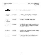
Страница 14: ...m includes Detector DAS FPS 100 BIRP and AP I O Direction18007 Display Includes keyboard A N Controller GAIDS trackball and W L control MI 10 MultiFormat Vendor Supplied Matrix Camera Direction14712 PPI Includes information for all CT 8800 and CT 9800 PPI boards Direction14763 Datalink Includes all service related material for CT 8800 and CT 9800 Datalink The format discussed in the following para...

Страница 15: ...ER 6 Describes jumper settings and device code switch settings etc in addition to the conventional adjustment procedures for subsystem components CHAPTER 7 Schematic diagrams of subsystem interconnect and circuit boards within the subsystem CHAPTER 8 Procedures for subsystem level troubleshooting to aid in determining which field replaceable unit has failed CALIBRATION FIELD REPLACEMENT FIELD REPL...

Страница 16: ...GE MEDICAL SYSTEMS CT 9800 QUICK SYSTEM MANUAL Rev 1 Direction 18000 i A 6 THIS PAGE INTENTIONALLY LEFT BLANK ...

Страница 17: ...r Interlocks 4 2 13 2 7 2 7 Emergency Off 4 2 13 3 DATA PROCESSING 4 3 1 3 1 Power Checks 4 3 1 3 2 Alpha Numeric System 4 3 11 3 3 S 140 Power Up Self Test 4 3 11 3 4 Initial Mag Tape Check 4 3 11 3 5 Initial ZEBRA Disk Drive Check 4 3 14 3 6 S 140 CPU Diagnostics 4 3 18 3 7 Final ZEBRA Disk Drive Checkout 4 3 24 3 8 Argus Disk Drive Checkout 4 3 25 3 9 ACE General Diagnostic Tape 4 3 27 3 10 Fin...

Страница 18: ...ication and Alignment Check 4 9 4 9 6 Keyboard Layouts 4 9 5 10 LOAD FROM COLD PROCEDURE SOFTWARE LOAD 4 10 1 11 REGEN 4 11 1 12 IMAGE PERFORMANCE VERIFICATION 4 12 1 12 1 General Requirements 4 12 1 12 2 Required Phantoms 4 12 3 12 3 Air Calibration 4 12 3 12 4 Phantom Self Calibration 4 12 4 12 5 Phantom Calibation 4 12 6 12 6 Means and Standard Deviations 4 12 8 12 7 Beam Hardening 4 12 13 12 8...

Страница 19: ... to determine symptoms of a failure prior to attempting to perform any service adjustments or troubleshooting Also a post diagnostic check to ensure proper operation has been restored If a step in the procedure fails its measurement refer to Chapter 6 Adjustments of this manual or Chapter 8 Diagnostics of this manual to restore operation After operation is restored refer back to this chapter and v...

Страница 20: ...ther of these sections require special reporting by the assembler A letter in the X RAY column however means that the respective component is certified under section 1020 30 as Diagnostic X Ray systems and their major components and must be reported on form FD 2579 The letter designates the code for the type of certified component Specific instructions on reporting of these certified components ar...

Страница 21: ... 82 B Tube Housing Assembly 3 Separate nameplate with assembly date and H H S certification no model or serial number F X Ray Control 4 Main Table assembly is HHS certified after August 1985 and nameplate relocated below side H High Voltage Control covers J Table 5 Reported as Master Control with model and serial number in item 4b 4c and 4d of FDA K Cradle form 2579 8 82 for all CT systems N Other...

Страница 22: ...ameplate with assembly date and H H S certification no model or serial number 4 Main Table assembly is HHS certified after August 1985 and nameplate relocated below side covers 5 Reported as Master Control with model and serial number in item 4b 4c and 4d of FDA form 2579 8 82 for all CT systems 6 QA and Performance Phantom replaces Resolution and Linearity after August 1985 CODES FOR TYPE OF X RA...

Страница 23: ...ust 1985 and reported A Beam Limiting Device In item 4e under Beam Limiting Device on FDA form 2579 8 82 B Tube Housing Assembly 3 Separate nameplate with assembly date and H H S certification no model or serial number F X Ray Control 4 Main Table assembly is HHS certified after August 1985 and nameplate relocated below side H High Voltage Control covers J Table 5 Reported as Master Control with m...

Страница 24: ...ugust 1985 and reported A Beam Limiting Device In item 4e under Beam Limiting Device on FDA form 2579 8 82 B Tube Housing Assembly 3 Separate nameplate with assembly date and H H S certification no model or serial number F X Ray Control 4 Main Table assembly is HHS certified after August 1985 and nameplate relocated below side H High Voltage Control covers J Table 5 Reported as Master Control with...

Страница 25: ...GE MEDICAL SYSTEMS CT 9800 QUICK SYSTEM Rev 10 Direction 18000 4 1 5B THIS PAGE IS LEFT BLANK INTENTIONALLY ...

Страница 26: ...GE MEDICAL SYSTEMS CT 9800 QUICK SYSTEM Rev 4 Direction 18000 4 1 6 TABLE 4 1 2 Sheet 1 CT 9800 SYSTEM OPTIONS COMPONENT NAMAEPLATES WITH MODEL SERIAL AND H H S CERTIFICATION ...

Страница 27: ...GE MEDICAL SYSTEMS CT 9800 QUICK SYSTEM Rev 13 Direction 18000 4 1 7 TABLE 4 1 2 Sheet 2 CT 9800 SYSTEM OPTIONS COMPONENT NAMAEPLATES WITH MODEL SERIAL AND H H S CERTIFICATION ...

Страница 28: ...GE MEDICAL SYSTEMS CT 9800 QUICK SYSTEM Rev 4 Direction 18000 4 1 8 TABLE 4 1 3 MODIFICATION NAMEPLATES ADDED TO CT 9800 SYSTEM OR OPTION COMPONENTS ...

Страница 29: ...0B Ch 6 Sec 9 6 SM 9800B Ch 6 Sec 9 6 Dir 18000 Ch 6 Sec 9 6 Beam on Window SM 9800B Ch 6 Sec 9 5 SM 9800B Ch 6 Sec 9 5 Dir 18000 Ch 6 Sec 9 5 2 SID SM 9800B Ch 6 Sec 9 9 Not Applicable Not Applicable Scan increment Accuracy Not Applicable SM 9802B Ch 4 Sec 6 Dir 18005 Ch 4 Sec 6 Alignment Light Visualization Not Applicable SM 9800B Ch 4 Sec 9 4 Dir 18000 Ch 4 Sec 9 4 Scan Plane Reference Not Appl...

Страница 30: ...GE MEDICAL SYSTEMS CT 9800 QUICK SYSTEM Rev 4 Direction 18000 4 1 10 THIS PAGE LEFT INTENTIONALLY BLANK ...

Страница 31: ...ne Printer Power plug disconnected Operator Console Power plug disconnected Diagnostic Console Power plug disconnected Multiformat Camera Power plug disconnected MPX Pwr Unit Fuses removed Fuses removed A7 F16 F17 F18 F19 F20 2 1 Temperature 1 During installation and start up of the CT system it is imperative that adequate temperature checks be made to assure that the environment meets specificati...

Страница 32: ...icles from getting in pack area b The cleaning procedure for the DGC Argus disk storage unit is Remove front cover panel Carefully peel the coarse air filter off the Velcro strip on the lower portion of the front of the chassis WARNING Damage to the disk drive will occur if the disk drive is operated without the coarse air filter installed on the front cover or if the coarse air filter is contamin...

Страница 33: ...re use In computer environment e Relative humidity All Areas 30 60 operating limits f Temperature rate 5 F Hr of Change Max 3 C g Room temperature 5 F Max Gradient 3 C h Relative humidity rate of change 5 RH Hr Max 2 2 Power Line Checks 1 It is assumed that during the pre installation site checks the power source for the system was checked for mean voltage as well as any line voltage disturbance 2...

Страница 34: ...nditions of line voltage and load Voltage Surges Transient voltage variations caused by external loads must not exceed 5 nor exceed 5 cycles duration and not occur more than 10 times per hour Frequency 60 0 5 Hz 50 Hz 0 5 Hz 5 Monitor the power lines on an oscilloscope and verify that there is no significant distortion noise or transients present Monitor on both a long and short time base Generall...

Страница 35: ... Printer and CSCGP All other display or Computing Options and CSCGP Max DC resistance of 0 025 ohm between Vault Ground and SPGP SPGP and CTRGP Table and CTRGP Gantry and CTRGP Any room facility patient ground points and PGP Ground Definitions System Power Ground Point SPGP This is in the PDU on A2TS1 Computer System Component Ground Point CSCGP This is in the bottom of the Main Computer Cabinet X...

Страница 36: ...aker and rearrange connections at the PDU Switch ON A1 breaker and recheck 3 Switch OFF the A1 main breaker 4 Install the PDU Fuses A3 F1 F2 F3 F4 F5 F6 5 Ensure that T1 transformer in the PDU tappings are set according to the line voltage measured in Step 2 and the Table 4 2 1 6 Switch ON A1 breaker 7 Ensure input line protection light A3 DS1 DS2 DS3 are ON PDU A3 parrel Note If the supply is a D...

Страница 37: ...F10 F11 F12 F13 F14 F15 A1 F1 F2 F3 F5 F6 A4 F2 Ensure voltages correspond to those voltages obtained in Steps 9 10 Caution PDU circuit breakers are overload trip devices Do not force breaker to remain on Investigate overload 17 At the PDU switch on circuit breaker CB9 Filament Supply 18 At the PDU on A2 terminal panel measure and note voltage at A2TS5 14 15 Ensure voltage is 230 18 4 Volts 19 At ...

Страница 38: ...1 W3 A B C N A B C N A B N B C N C N A N C N C N 208 3 208 3 120 2 120 2 120 120 120 120 NOTE DU2 Power not used for Argus Disk Drive 28 At the Disc Drive Unit wall outlets DU1 W2 DU2 W10 using the phase sequence indicator verify the correct phase sequence 29 At the REM panel press the X Ray and drives circuits ON Verify the ON indicator switch illuminates 30 At the PDU A3 panel verify relay A3K3 ...

Страница 39: ...breaker MEASURE AND NOTE THE OUTPUT VOLTAGES Ensure they are 208 16 6 Volts 39 Break OFF position all circuit breakers at the PDU as listed below DU1 CB13 DU2 CB12 CC1 CB11 CC2 CB10 OC CB6 DC CB5 MC CB4 LP CB3 Plug all units into wall outlets Remake the above circuit breakers NOTE DU2 Power not used for Argus Disk Drive 40 This procedure is now finished Proceed to individual equipment functional c...

Страница 40: ...S 2 TS 2 TS 2 F5 F4 F6 TS 2 TS 2 TS 2 TS 2 TS 2 TS 2 TS 2 TS 2 TS 2 TS 2 TS 2 TS 2 TS 2 TS 2 TS 2 TS 2 TS 2 TS 2 AC 2000 V AC 2000 V AC 2000 V AC 2000 V AC 2000 V AC 2000 V AC 2000 V AC 2000 V AC 2000 V AC 2000 V AC 2000 V AC 2000 V AC 2000 V AC 2000 V AC 2000 V AC 2000 V AC 2000 V AC 2000 V AC 200 V AC 200 V AC 200 V AC 200 V AC 200 V AC 200 V AC 200 V AC 200 V AC 200 V AC 200 V AC 200 V AC 200 V...

Страница 41: ...1 B C T1 C C F1 F2 F3 F5 F6 F2 14 9 8 X Y Z X X Z X Y Y Z L L L L L1E L2E L3E 3 1 2 3 TS2 TS2 TS2 TS2 TS2 TS2 15 10 9 Y Z X Y Y X W W W W N N N N L2E L3E L1E 4 2 3 1 AC200 V AC200 V AC200 V AC200 V AC200 V AC200 V AC2000V AC200 V AC200 V AC2000V AC2000V AC2000V AC2000V AC2000V AC2000V AC200 V AC200 V AC200 V AC200 V AC200 V AC200 V AC200 V AC200 V AC2000V AC2000V AC2000V AC200 V AC2000V AC2000V AC...

Страница 42: ... phase sequencing NOT required 5 Connect XG1A7A1 JP1 per Table 4 2 3 6 Connect XG1A7A1 JP2 per Table 4 2 3 7 Measure voltages at L1E L2E and L3E using a 0 750 AC voltmeter of 3 4 accuracy Verify that the highest line to line voltage must not exceed 1 02 times the lowest voltage For example if the lowest voltage is 474 the highest voltage allowed would be 474 x 1 02 483 5 Volts TABLE 4 2 3 LINE CON...

Страница 43: ... A3 panel relays A3 K1 K2 K3 de energize At the REM panel the OFF red indicator light and the green ON goes out This condition is maintained even when the temperature returns to normal level 2 7 Emergency OFF 1 SEO system emergency OFF Switch A1 Main Breaker ON Ensure that SEO operation de energizes the A1 Main Breaker Repeat this several times to ensure correct operation 2 Table Emergency OFF Ope...

Страница 44: ...GE MEDICAL SYSTEMS CT 9800 QUICK SYSTEM Rev 1 Direction 18000 4 2 14 THIS PAGE LEFT BLANK INTENTIONALLY ...

Страница 45: ...g out the entire subsystem particularly at installations 3 1 Power Checks RDCP Reconstruction Data Collection Processor an Array Processor with additional GE capabilities ASSUMPTIONS 1 Installation and leveling are complete for the Main computer Cabinet CC1 the RDCP Cabinet CC2 the primary Disk Drive DU1 the Optional Secondary Disk Drive DU2 and the Operator s Console OC per the CT 9800 System Man...

Страница 46: ...GE MEDICAL SYSTEMS CT 9800 QUICK SYSTEM Rev 9 Direction 18000 4 3 2 ILLUSTRATION 4 3 1 CC1 POWER SWITCHES ...

Страница 47: ...GE MEDICAL SYSTEMS CT 9800 QUICK SYSTEM Rev 9 Direction 18000 4 3 3 ILLUSTRATION 4 3 2 OPERATOR S CONSOLE POWER SWITCH ...

Страница 48: ...f DG s Field Engineer s Maintenance Manual located in the S 140 Manual Volume 1 Part 2 for troubleshooting hints Optional Measure the power supply voltages at the test plug J1 on the front of the Power Supply Circuit Board as shown in Illustration 4 3 3 Voltage levels should be measured with a DVM ripple should be measured with a scope with AC coupling Pin 9 of J1 should be used as the ground refe...

Страница 49: ...GE MEDICAL SYSTEMS CT 9800 QUICK SYSTEM Rev 9 Direction 18000 4 3 5 ILLUSTRATION 4 3 3 ...

Страница 50: ...ve Drive configuration can be identified by rating plate Scanner Disk Drive model 46 196866P4 200 volts IC Disk Drive model 46 196866P2 380 volts Add on 50 Hz Disk Drives will be shipped configured for 380 volt operation with instructions and material to set up drive for 200 volt operation See Illustration 4 3 5B to check internal drive jumpers a Ensure that the control panel switches on the front...

Страница 51: ...panel When the spindle has started to rotate press the STOP switch The spindle should have been rotating counter clockwise CCW If the spindle rotates clock wise CW the phasing on the incoming 3 phase power to the drive has probably been reversed and must be corrected so that it is correct both at the wall outlet and inside the drive Note that the spindle drive belt may come off if the spindle rota...

Страница 52: ... ADAPTER BACKPLANE Viewed from rear of cabinet 5 Argus Disk Unit Note If an Argus Disk drive is not present in your system proceed to step 6 a Ensure the Front Panel switch is in the OFF position Refer to Illustration 4 3 7 b Locate Argus Cabinet and Argus Chassis AC Circuit Breakers and ensure they are OFF Refer to Illustration 4 3 8 c For initial installation of Argus Disk Drive verify Voltage J...

Страница 53: ...GE MEDICAL SYSTEMS CT 9800 QUICK SYSTEM Rev 9 Direction 18000 4 3 9 ILLUSTRATION 4 3 8 ARGUS CABINET BREAKERS ...

Страница 54: ...E Disk Drive is not present in your system proceed to step 7 a Turn ON the Power switch at the front of the ACE disk drive b Observe that the Power on light is ON and the light on the front of the ACE disk drive is on momentarily then goes off c Ensure that all LEDs on the ACE controller board are OFF If they are ON or Flashing a problem has been detected ...

Страница 55: ...pansion Chassis Illustration 4 3 3 3 The PWR and RUN LEDs should light and the RUN LED should stay lit for about 1 second before going out 4 The following should be displayed on the alpha numeric monitor at the Operator s Console OK 000000 This indicates that the self test was completed and no problems found 5 If the self test was not completed normally printout of Step 4 is not visible on A N Mon...

Страница 56: ...in the HIGH position the DENSITY LED is lit d Verify that with no tape mounted on the lower supply reel the WRITE LOCK LED is lit e Mount a tape with the yellow write enable ring installed and verify that the WRITE LOCK LED goes out 2 Mount and load scratch tape a Mount a scratch tape with a yellow write enable ring installed on the supply reel and verify that the tape seats firmly on the hub when...

Страница 57: ...nual contained in the 6026 Mag Tape Manual Part 4 ILLUSTRATION 4 3 11 VACUUM COLUMN ALIGNMENT d Press the ON LINE switch and verify that the ON LINE LED and the READY LED both light 3 Check Communication with S 140 a Ensure that the S 140 is in Virtual Console mode and the Virtual Console prompt is present on the alpha numeric screen If not go to the S 140 front console hold the UNLOCK switch and ...

Страница 58: ...d the tape will rewind to the BOT marker c When the tape is at BOT press and hold the UNLOAD switch down until the tape has completely rewound onto the supply reel d Dismount the scratch tape 3 5 Initial ZEBRA Disk Drive Check IMPORTANT BE SURE TO TURN OFF THE ODD optical disk and THE MDD OD magnetic disk prior to executing and dg diagnostics or exercizers These programs will write data to and des...

Страница 59: ...TE ENABLED b Mount and load the DTOS tape If necessary refer to DTOS Vol 1 Part 1 for details c At the prompt i observe the following and type the underlined responses if a line printer is available and a print out desired type a 5 CR in response to the statement SET SWPAK LOAD ZDKP FMTR CR LOAD ZDKP FMTR REV nn SET SWPAK AS PER SECT 8 0 OR HIT CR TO CONTINUE Note Set switch 1 to disable CR loopin...

Страница 60: ...0 SECTORS READ 64 SECTORS WRITTEN 586280 BAD SECTOR CYL HEAD SECTOR ADDRESS ERROR CYL HEAD SECTOR 0 BAD SECTORS ON CYLINDER 0 0 BAD SECTORS MAX ON CYLINDER 0 0 BAD SECTORS MAX ON SURFACE 0 0 BAD SECTORS TOTAL 0 HARD DATA ERRORS 11 BITS Dual Drive systems this printout will be followed immediately by the similar status for Drive 1 If an ECC error is detected a message similar to the following will ...

Страница 61: ... DATA ERRORS CYL HEAD SECT COUNT 646 5 16 1 ADDRESS ERROR CYL HEAD SECT COUNT 0 BAD SECTORS ON CYLINDER 0 1 BAD SECTORS MAX ON CYLINDER 646 1 BAD SECTORS MAX ON SURFACE 5 1 BAD SECTORS TOTAL 0 HARD DATA ERRORS 11 BITS f When the requested number of passes is complete the status will be posted as if you typed L and it will be followed by HALT WAS ENCOUNTERED 1101 TO RESTART GIVE ADDRESS R 0 To exit...

Страница 62: ...S 140 CPU Diagnostics IMPORTANT BE SURE TO TURN OFF THE ODD optical disk and THE MDD OD magnetic disk prior to executing DG diagnostics and or exercizers These programs will write data to and destroy the content of the Optical disk media or the MDD This section assumes that the disk drive is loaded with a formatted scratch pack for Zebra Systems the pack is spinning and the drive is READY and WRIT...

Страница 63: ...R 0 S 140 TYPE 1 S200 TYPE 2 S230 TYPE 3 S250 TYPE k Type 0 CR l Observe TOP OF MEMORY 077777 GE DTOS REV nn ADES ONLY g Type 100022L h FILENAME ADES Enter a Carriage Return i Observe Copyright C Data General Corp 1983 1984 All rights reserved Licensed Material Property of Data General CPU is Eclipse S 140 ADES automatically determines CPU configuration Memory Size is 256 KW Run Autosizer Y N Y En...

Страница 64: ...ON NOVA INSTRUCTION SET EXERCISER PASS 1 LOAD and etc ADES ONLY 2 Run one pass of diagnostics typing the underlined ADES CLI RUN Enter a Carriage Return ADES Script Builder REV 1 0 Building Script Script Built Prior X 8 0 NESISV 14 00 NESISV 23 0 NEFADRX 4 0 EASIS_X1 3 0 Note Underscore Do not use a space or other character EASIS_X2 3 0 Note Underscore Do not use a space or other character EASIS_X...

Страница 65: ...or troubleshooting information 3 Run ECLMORT L overnight DTOS ONLY This program is not recognized by ADES For ADES the similar program is called SEARCH which is destructive to disc contents a If the DTOS prompt is not on the terminal reboot the DTOS tape as follows Check that the tape is loaded at BOT the BOT light is lit and ONLINE the READY light is lit If tape is loaded but not at BOT RESET the...

Страница 66: ...g LOAD ECLMORT L CR When the program is loaded an will be present on the alpha numeric screen as a prompt d Remove DTOS tape from drive and replace with a scratch tape When scratch tape is loaded ensure tape drive is at BOT ON LINE and READY e Proceed with the program by typing P at the prompt as follows P CR f Observe ECLMORT L MULTIPROGRAMMING RELIABILITY TEST LONG VERSION TOTAL 1K S 128 USING M...

Страница 67: ...ROR CORRECTION 2 CHECKER BOARD RANDOM TEST 3 EIS MRI TEST 4 ARITHMETIC TEST 5 ADDRESS TEST 6 EXTENDED ADDRESSING TEST 12 FLT PT TEST 14 LER INSTR MMPUI ERROR TEST 15 SC MEMORY TEST 20 6061 SERIES DISC DEV 27 21 MAG TAPE TEST DEV 22 23 REAL TIME CLOCK 22 LINE PRINTER DEV 17 24 TTY TEST ENTER OPTIONS CR TO CONTINUE h Type CR to continue i While the program is running passes and elapsed run time can ...

Страница 68: ...nd THE MDD OD magnetic disk prior to executing and DG diagnostics or exercizers These programs will write data to and destroy the content of the Optical disk media or the MDD 1 Verify Servo Null and Alignment Refer to Chapter 6 Section 3 of this manual if necessary a Verify the Servo Null as described in Chapter 6 Section 3 b Check the Head Alignment using the procedure in Chapter 6 Section 3 Head...

Страница 69: ...US Disk Drive Checkout ADES ONLY IMPORTANT BE SURE TO TURN OFF THE ODD optical disk and THE MDD OD magnetic disk prior to executing and DG diagnostics or exercizers These programs will write data to and destroy the content of the optical disk media or the MDD 1 Ensure Argus Disk Drive front panel power switch is in the OFF 0 position 2 Locate cabinet circuit breaker on lower rear panel of cabinet ...

Страница 70: ...ted to the console Run time for Controller only testing is 0 5 minutes 7 Reset computer and load 6236 FUNC for diagnostics track only run 1 complete pass This test should be run on both Argus Drives of a Dual Drive system LOAD 6236 FUNC CR LOAD 6236 FUNC REV nn HELP YES NO NO SET SWREG AS PER 8 0 HIT CR TO CONTINUE CR OCTAL OR HEX DISK MEMORY DATA MODE OCT HEX OCT DEVICE CODE OCTAL 24 UNITS TO TES...

Страница 71: ...he system configuration has been changed number of drives HTD upgrade etc The configuration is written to EEPROM resident on the controller board and should remain there unless a problem develops The ACE disk drive uses a standard SCSI interface that is provided by the Zetaco Controller Board Host Controller The controller boards for the ACE Disk and the Optical Disk have different Firmware Theref...

Страница 72: ...elf Test a corresponding LED is lit to report the failure status Ill 4 3 13 ILLUSTRATION 4 3 13 CONTROLLER BOARD CONFIGURATION There are two sets of LED s on the Controller to indicate which side of the interface the problem was detected These functions of each LED is as follows SCSI CPU Self Test Red LED on the left SCSI Bus Busy Green LED Not Used Yellow LED Host Side CPU Self Test Red LED on th...

Страница 73: ...Bus RAM EN Read or Write problem 2 HI SPEED BUFFER1 Data read buffer 1 did not compare with data written Buffer ram chips HS BUF EN HS Address counters ADR Bus SD Bus or BO Bus 3 HI SPEED BUFFER2 Data read from buffer 2 did not compare with data written Buffer ram chips HS BUF EN HS Address counter ADR Bus SD Bus or B1 Bus 4 DONE The done flip flop did not set or did not clear when told to Flip fl...

Страница 74: ...d not compare with data written or a forced 5380 interrupt was not detected 6 DYNAMIC RAM PARITY DRAM parity error interrupt not successfully forced or cleared 7 NOT USED 8 NOT USED Operational Errors Some error conditions may occur while the board is executing M level programs These errors will be reported on the Left RED LED The error codes are listed in Table 4 3 3 The error can be cleared by r...

Страница 75: ...econd drive Execute this file to reload MV7800 Microcode Initial Installation On initial installation the following sequence should be followed 1 Configure as a Single or Dual Ace drive system STD CT9800 or HTD 2 Format the disk using the A Analyze option within the formatter program 3 Run the Initializer using the Z ZDKINIT option 4 Initialize the controller and disk and reload microcode before b...

Страница 76: ...the GESCSI controller to your particular environment The GESCSI controller includes an electrically erasable prom EEPROM which contains certain facts This program lets you list the cur rent facts modify those that you want changed and record the new facts onto the EEPROM The HELP command on the main menu provides information both on what to do and how to do it If this is the first time you have ru...

Страница 77: ... wish to enter your own values A reasonable sequence of events might be 1 Select H on Command Menu Read through HELP until you are comfortable 2 Select L on Command Menu This will let you see the values currently set on the controller 3 Select N on Command Menu if you have a printer at device code 17 All questions and responses will then be Logged to this printer 4 Select D on Command Menu A list ...

Страница 78: ...EN to END disk selection CT CR How many drives in this system 1 4 1 CR For 1 Disk system Enter BMC priority 0 lowest 7 highest S280 and MV4000 0 3 only 5 CR What is the throttle burst rate 32 CR What is the throttle break count 4 CR Current Configuration Facts Logical Logical Logical Logical Unit 0 Unit 1 Unit 2 Unit 3 Heads 1 1 1 1 Sectors 128 128 128 128 Cylinders 4581 0 0 4 Formt d megs 300 0 0...

Страница 79: ... Magnetic Resonance M1 MR using 1 ST34520N Microcode on logical unit 0 BMC priority 5 Throttle burst rate 32 Break count 4 Enter command to see choices U CR Updating Please wait SCSI DEV 1 Y or N Y CR Enter BMC priority 0 lowest 7 highest S280 and MV4000 0 3 only 5 CR What is the throttle burst rate 32 CR What is the throttle break count 4 CR Current Configuration Facts Logical Logical Logical Log...

Страница 80: ...R using 1 ST34520N Microcode on logical unit 0 BMC priority 5 Throttle burst rate 32 Break count 4 Enter command to see choices U CR Updating Please wait SCSI DEV 1 Y or N Y CR Enter BMC priority 0 lowest 7 highest S280 and MV4000 0 3 only 5 CR What is the throttle burst rate 32 CR What is the throttle break count 4 CR Current Configuration Facts Logical Logical Logical Logical Unit 0 Unit 1 Unit ...

Страница 81: ...Logical Logical Unit 0 Unit 1 Unit 2 Unit 3 Heads 1 1 1 1 Sectors 128 128 128 128 Cylinders 9161 0 0 0 Formt d megs 600 0 0 0 Logical blks 1172316 0 0 792 To see the partitioning of a logical unit enter the unit number 0 CR 0 Logical unit 0 Ending Blk Offset SCSI Dev Unit Partition 0 1172507 0 0 0 To see the partitioning of a logical unit enter the unit number 1 CR Logical unit 1 Ending Blk Offset...

Страница 82: ...ces A nalyze Disk R elocate blocks F ormat only Enter your selection A A CR FORMAT YES NO CR Retain any previously relocated sectors If you do not retain the previously relocated sectors it is recommended that a full five pattern analysis be done in order to relocate all the bad sectors that were previously being handled YES NO CR THE DATA PATTERNS LISTED BELOW ARE USED IN THE ORDER LISTED AAAA 25...

Страница 83: ...or bits 4 and 5 are set to 01 If a begin is issued the controller boots its processor code from disk If an error occurs during the boot a PIO command execution error results and the controller sets bits 4 and 5 thru 10 1000 Begin command executed successfully controller is ready but not initialized Legal commands are Diagnostic Mode 024 Set Mapping information 026 Get Mapping information 027 Unit ...

Страница 84: ...T 4 BIT 3 BIT 2 BIT 1 BIT 0 STATUS REPRESENTED 0 0 0 0 0 0 0 0 Good 0 0 0 0 0 1 1 0 Check Condition 0 0 0 0 1 0 0 0 Busy 0 0 0 1 1 0 0 0 Reservation Conflict The COMMAND STATUS description is as follows Good Indicates the WREN IV has successfully completed execution of the command Check Condition Any error exception or abnormal condition that causes sense data to be set will cause a Check Conditio...

Страница 85: ...Q uit Enter a Command Selection C Cmd List E CR Enter the device code 24 CR Start initialization of controller Micro code rev 3 00 End initialization of controller Unit 0 is Ready Select YES NO YES CR Note Use Z without selecting any units to initialize the controller only Command choices Z DKINIT ZDKINIT INSTALL MICROCODE INIT SOFT LOG A NALYZE DISK R ELOCATE BLOCKS M ICROCODE INSTALL ONLY ENTER ...

Страница 86: ...de rev 3 00 End initialization of controller Unit 0 is Ready Select YES NO YES CR Note Use Z without selecting any units to initialize the controller only Command choices Z DKINIT ZDKINIT INSTALL MICROCODE INIT SOFT LOG A NALYZE DISK R ELOCATE BLOCKS M ICRO CODE INSTALL ONLY ENTER YOUR SELECTION Z CR UNIT 0 IS SELECTED UNIT 1 IS READY Select YES NO YES CR Command choices Z DKINIT ZDKINIT INSTALL M...

Страница 87: ... C HIT CR KEY TO CONTINUE c To dismount the DTOS tape press RESET to take the drive off line press BOT to rewind the tape then press and hold the UNLOAD switch to wind the tape onto the supply reel d Mount a 10 reel of blank tape containing the yellow write enable ring Press BOT to load the vacuum columns When the tape is at BOT press ONLINE e At the Operator s Console hit the CR key The tape shou...

Страница 88: ...E MAPS TO BE EXERCISED YES NO testing device select 22 UNITS 0 502 SEQUENTIAL MEDIA VERIFICATION WITH OPTIONS OPTIONS ARE DATA SEE 4 DATA PATTERNS TEST TO END OF TAPE EOT YES NO IF N0 400 RECORDS ARE WRITTEN READ WORD COUNT RAN MAX OR N CR 1000 503 COMMAND STRING 505 RUNALL 506 SPACING EXERCISER 507 SHORTENED RUNALL W O EOT CHECK 510 ERROR LOG RECOVERY MORE HELP 0 6 0 EXIT 1 INDEX 0 START ADDRESS ...

Страница 89: ...tailor the GESCS controller to your particular environment The GESCSI controller includes an electrically erasable prom EEPROM which contains certain facts This program lets you list the current facts modify those that you want changed and record the new facts onto the EEPROM The HELP command on the main menu provides information both on what to do and how to do it If this is the first time you ha...

Страница 90: ... selected if you wish to enter your own values A reasonable sequence of events might be 1 Select H on Command Menu Read through HELP until you are comfortable 2 Select L on Command Menu This will let you see the values currently set on the controller 3 Select N on Command Menu if you have a printer at device code 17 All questions and responses will then be Logged to this printer 4 Select D on Comm...

Страница 91: ...m 1 4 1 CR For 1 Disk system Disk type s accepted Enter BMC priority 0 lowest 7 highest S280 and MV4000 0 3 only 5 CR Field accepted What is the throttle burst rate 32 CR What is the throttle break count 4 CR Current Configuration Facts Logical Logical Logical Logical Unit 0 Unit 1 Unit 2 Unit 3 Heads 1 1 1 1 Sectors 128 128 128 128 Cylinders 4581 0 0 4 Formt d megs 300 0 0 0 Logical blks 586062 0...

Страница 92: ...acts Logical Logical Logical Logical Unit 0 Unit 1 Unit 2 Unit 3 Heads 1 1 1 1 Sectors 128 128 128 128 Cylinders 9161 0 0 8 Formt d megs 600 0 0 0 Logical blks 1172316 0 0 726 To see the partitioning of a logical unit enter the unit number CR ______________________________________________________________________ Microcode on logical unit 0 BMC priority 5 Throttle burst rate 32 Break count 4 Enter ...

Страница 93: ...nit 0 Unit 1 Unit 2 Unit 3 Heads 1 1 1 1 Sectors 128 128 128 128 Cylinders 8538 611 0 20 Formt d megs 559 39 0 1 Logical blks 1092614 78001 0 2337 To see the partitioning of a logical unit enter the unit number CR ______________________________________________________________________ Microcode on logical unit 0 BMC priority 5 Throttle burst rate 32 Break count 4 Enter command to see choices U CR U...

Страница 94: ...gical Unit 0 Unit 1 Unit 2 Unit 3 Heads 1 1 1 1 Sectors 128 128 128 128 Cylinders 9161 0 0 0 Formt d megs 600 0 0 0 Logical blks 1172316 0 0 792 To see the partitioning of a logical unit enter the unit number CR ______________________________________________________________________ Microcode on logical unit 0 BMC priority 5 Throttle burst rate 32 Break count 4 Enter command to see choices U CR Upd...

Страница 95: ...GE MEDICAL SYSTEMS CT9800 QUICK SYSTEM Rev 24 Direction 18000 4 3 49B This page left intentionally blank ...

Страница 96: ... to format Command choices A nalyze Disk R elocate blocks F ormat only Enter your selection A A CR FORMAT YES NO CR Retain any previously relocated sectors If you do not retain the previously relocated sectors it is recommended that a full five pattern analysis be done in order to relocate all the bad sectors that were previously being handled YES NO CR THE DATA PATTERNS LISTED BELOW ARE USED IN T...

Страница 97: ...ion C Cmd List L CR Run time 0 hrs 14 mins 4 secs 4 tenths Device Code 24 SCSI dev number 0 Unit number 0 State Active Modes FORMAT Formatting waiting to be started of blocks analyzed 0 of Hard errors reported 0 of Soft errors reported 0 Device Code 24 SCSI dev number 1 Unit number 0 State Active Modes FORMAT Formatting in process of blocks analyzed 0 of Hard errors reported 0 of Soft errors repor...

Страница 98: ...tenths Device Code 24 SCSI dev number 0 Unit number 0 State Active Modes FORMAT ANALYZE REG A REG B REG C OPERATION 0 0 1203 STATUS 0 0 15203 Execution status Reset complete Unable to Load Micro code Decode the 015203 status Word as follows See PIO Errors later in this section for more information NOTE The X eq and error log option is described later in this section ...

Страница 99: ...ction C Cmd List E CR Enter the device code 24 CR Start initialization of controller Micro code rev 3 00 End initialization of controller Unit 0 is Ready Select YES NO YES CR NOTE Use Z without selecting any units to initialize the controller only Command choices Z DKINIT ZDKINIT INSTALL MICROCODE INIT SOFT LOG A NALYZE DISK R ELOCATE BLOCKS M ICROCODE INSTALL ONLY ENTER YOUR SELECTION Z CR UNIT 0...

Страница 100: ...0 Sector Count 42 Memory Address 55206 Command Write Page Table address 0 Returned XFER count 0 Physical Block 0 Async Status 3 CB Execution Error Hard Errors CB Status 100001 Any CB Hard Execution Error CB Done Bit CB Error 40000 DRIVE INTERFACE FAULT CB Unit Status 22000 Ready Port Reserved Bit LSB Disk Error 1000 ENTER A COMMAND SELECTION C CMD LIST Run Time 0 hrs 0 mins 5 secs 3 tenths Device ...

Страница 101: ... C HIT CR KEY TO CONTINUE c To dismount the DTOS tape press RESET to take the drive off line press BOT to rewind the tape then press and hold the UNLOAD switch to wind the tape onto the supply reel d Mount a 10 reel of blank tape containing the yellow write enable ring Press BOT to load the vacuum columns When the tape is at BOT press ONLINE e At the Operator s Console hit the CR key The tape shou...

Страница 102: ...E MAPS TO BE EXERCISED YES NO testing DEVICE SELECT 22 UNITS 0 502 SEQUENTIAL MEDIA VERIFICATION WITH OPTIONS OPTIONS ARE DATA SEE 4 DATA PATTERNS TEST TO END OF TAPE EOT YES NO IF NO 400 RECORDS ARE WRITTEN READ WORD COUNT RAN MAX OR N CR 1000 503 COMMAND STRING 505 RUNALL 506 SPACING EXERCISER 507 SHORTENED RUNALL W O EOT CHECK 510 ERROR LOG RECOVERY MORE HELP 0 6 0 EXIT 1 INDEX 0 START ADDRESS ...

Страница 103: ...erface at power up time If a failure is detected during Self Test a corresponding LED is lit to report the failure status These are two sets of LED s on the ODC Controller Board to indicate which side of the interface the problem was detected One interface is the ARZ or Argus interface This interface is allows the ERCC BMC card in 140 only or the ERCC BMC circuit on the MV7800 CPU board to communi...

Страница 104: ...ST POSSIBLE FAILURE 1 RAM TEST Data read from ram did not compare with written RAM chips ADR Bus SD Bus RAM EN Read or Write problem 2 HI SPEED BUFFER 1 Data read buffer 1 did not compare with data written Buffer ram chips HS BUF EN HS address counter ADR Bus SD Bus or B0 Bus 3 HI SPEED BUFFER 2 Data read from buffer 2 did not compare with data written Buffer ram chips HS BUF EN HS Address counter...

Страница 105: ... was not detected 6 DYNAMIC RAM PARITY DRAM parity error interrupt not successfully forced or cleared 7 NOT USED 8 NOT USED Operational Errors Some error conditions may occur while the board is executing M level programs These errors will by reported on the Left RED LED The error codes are listed in Table 4 11 3 The error can be cleared by Rebooting the Computer TABLE 4 11 2 ODC MODULE ERROR CODES...

Страница 106: ...TICAL MEDIA FOR RUNNING DIAGNOSTICS ETC SAVEWINCH ONLY SAVES THE DIRECTORY AND ADDRESS ETC INFORMATION THAT IS STORED ON THE MDD IT DOES NOT SAVE THE PATIENT IMAGES STORED ON THE OPTICAL MEDIA ITSELF THEREFORE IF YOU RUN SAVEWINCH BUT USE THE CUSTOMER OPTICAL MEDIA TO EXECUTE DIAGNOSTICS ETC YOU MAY WRITE INFORMATION TO THE CUSTOMERS OPTICAL MEDIA AND PREVENT IT FROM CLOSING EFFECTIVELY DESTROY AL...

Страница 107: ...2 CR Enter 2 to load the Configurator program WHAT IS THE OCTAL DEVICE CODE 34 CR Enter the Device Code ENTER COMMAND TO SEE CHOICES CR COMMAND MENU A CHANGE ALL FACTS B BMC priority C Operating System D Platter ID E Number of Optical Drives F Throttle burst count G Break Count H HELP Operations W Help What to do L List all Configuration facts N Start logging to printer O Stop logging to printer U...

Страница 108: ...u must press IORESET to re initialize the controller with the new values Do you want to configure another ODSS controller Y N N CR Press Reset on the CPU front panel and reboot the tape The UTILITY Program FILE PROGRAM 2 GEMOS CONFIGURATOR 3 GEMOS UTILITY FILE NUMBER 3 CR Enter 3 to load the Utility Program A DO ALL FORMAT INSTALL FIRMWARE DKINIT B FORMAT MAGNETIC DISK See GUIDELINES FOR USAGE C I...

Страница 109: ...IC DISK D INSTALL SCSI FIRMWARE ON MAGNETIC DISK E INITIALIZE DKINIT THE MAGNETIC DISK I INQUIRE THE DRIVE R RE INITIALIZE THE CONTROLLER P PLATTER COMPLETION PURGE OF MAGNETIC DISK H HELP L LOGGING TO THE PRINTER Q QUIT CHOICE R CR You must reinitialize the controller after a format Enter the drive code for disk controller 34 CR Controller Init Routine Controller reinitialized ENTER C TO CONTINUE...

Страница 110: ...and writes the directories to the allocated space on the optical media After the Purge function is complete the MDD directory area is empty and ready to attach another platter Caution Until the Optical Media is closed the Optical Media and the Magnetic Media are married That is neither contains all the information that has been stored on the magnetic Therefore if the MDD is replaced prior to optic...

Страница 111: ...r programming purposes 6 thru A DESCRIPTOR BYTE 1 DESCRIPTOR BYTE 9 DESCRIPTOR BYTE 0 DESCRIPTOR BYTE 8 B SCSI STATUS BYTE C INTERFACE ERRORS D SCSI MESSAGE OUT Last message to ODD E SCSI MESSAGE IN Last message from ODD F INTERFACE STATUS Status of the SCSI command 10 thru 17 SENSE BYTE 1 SENSE BYTE 15 SENSE BYTE 0 SENSE BYTE 14 Error Log Entry Layout DESCRIPTOR BYTES WORDS 6 A contain the SCSI c...

Страница 112: ...sed INTERFACE STATUS WORD F contains general status of the SCSI command The bits are defined as Bit 15 SCSI Command Active Bit 14 DMA Transfer Active Bit 13 SCSI Command Complete Bit 12 Drive currently disconnected from ODC Bit 11 Command pending execution Bit 10 Arbitration lost ODC could not access the SCSI bus Bit 9 Abort command ODC issued an about command to the drive normal condition Bit 8 M...

Страница 113: ...g disk write failed 037 Unable to free up cache for pending disk write Rollout failed 03C Disk write error Cache write 046 Optical Read error during first sector concatenation 04B Optical Write error during first sector concatenation 050 Optical Read error during Last sector concatenation 055 Cache write error during Last sector concatenation 05F Error backing up SCRUB directory 069 Write to close...

Страница 114: ... key types Examine keys 1BA Magnetic key is set to error state A7 and optical key is set to active A4 1BD Non compare of EEPROM facts and magnetic disk facts 1C2 Error reading cache table to Magnetic 1C7 Error writing cache table to Magnetic 1CC Error writing SCRUB directory to magnetic 1D1 Error reading saved DKINIT sectors from magnetic 1D6 Error writing DKINIT sectors to cache 1DB Error backing...

Страница 115: ...or SCRUB retry s expired 0A8 Optical write error Platter change or reset detected 0B9 Cache entry error flag set to Magnetic READ WRITE or Optical READ error 0BE SCRUB area full 0C3 Cache read error 0C8 Failed writing SCRUB directory to Optical 0CD Failed writing COMPLETE keys to Optical less than 2 of 5 successful 0D2 Failed write of purged key to magnetic 0D7 Error backing up cache table to magn...

Страница 116: ...GE MEDICAL SYSTEMS CT 9800 QUICK SYSTEM Rev 14 Direction 18000 4 3 70 THIS PAGE IS INTENTIONALLY LEFT BLANK ...

Страница 117: ...ft and right axial beams are coincident 1 5mm 6 Move the sheet of paper forward across the external axial plane Check that left and right axial beams are coincident 1 5mm 7 At both internal and external axial positions check that the left and right coronal beams are coincident 3mm 8 Tilt gantry 20 and check coronal beams stay coincident 3mm 9 Extend cradle into sagital beam Check that sagital beam...

Страница 118: ... Alignment This procedure assumes alignment lights are aligned Verify that the correct table to gantry alignment is correct as follows 1 Center the 35 cm poly phantom using standard system software to 0 25mm 2 Press the LIGHTS button on the table verify the alignment lights are ON 3 Verify that the sagittal and coronal beam are coincident with the center lines on the phantom 4 Mark the intersectio...

Страница 119: ...GE MEDICAL SYSTEMS CT 9800 QUICK SYSTEM Rev 1 Direction 18000 4 9 3 ILLUSTRATION 4 9 1 LASER WARNING AND PRECAUTIONS ...

Страница 120: ...adle surface for the external and internal alignment light locations Note Footcandles x 10 76 lux 6 If the light reading s are greater than 500 lux reduce the room lighting to that level and repeat steps 3 and 4 If the light meter readings are 500 lux or less replace the laser light s and or their power supplies 9 5 Tomographic Plane Indication and Alignment Check H H S requirements state that the...

Страница 121: ...AN TIME BLANK DFOV DFOV DFOV 12 DELAY START BLANK BLANK BLANK BLANK 47 BLANK BLANK BLANK GRAY SCALE BLANK 48 BLANK BLANK BLANK BLANK BLANK 49 BLANK BLANK AMID AMID AMID 59 SCREEN SAVE SCREEN SAVE BLANK BLANK BLANK 65 GRAY SCALE GRAY SCALE GRAY SCALE CHANGE W L GRAY SCALE 77 BLANK BLANK SCREEN SAVE SCREEN SAVE SCREEN SAVE 78 BLANK BLANK BLANK BLANK OPTICAL DISK 79 BLANK BLANK BLANK BLANK DISPLAY OP...

Страница 122: ...GE MEDICAL SYSTEMS CT 9800 QUICK SYSTEM Rev 4 Direction 18000 4 9 6 ...

Страница 123: ...ent software to incorporate improvements or correct existing problems As above the old software can be replaced by doing a Load from Cold using the new software Operator entries which must be type are underlined and written in a different styled font i e typewriter font than the rest of the text which is in modern font e g DIR DAO means to type DIR DAO System responses are not underlined e g PLEAS...

Страница 124: ... not performing a disk drive replacement 4 Load Microcode MV7800 only Note Perform this step for first time install For subsequent LFC s omit this step if there are no suspected disk problems or if you are not performing a disk drive replacement 5 Install bootstrap loader onto the disk Note Perform this step for first time install For subsequent LFC s omit this step if there are no suspected disk ...

Страница 125: ...twice on the tape to provide backup if one set cannot be loaded back onto disk NOTE If the hospital name will be changed during the Load From Cold procedure the change will not be made on the Default files they must be changed separately R DIR DA0 CR Argus Ace DIR DZO CR Zebra R SAVEALL CR Follow directions on screen through completion of the program The data files being saved will be displayed tw...

Страница 126: ... high density selected on line and write enabled with a write ring on the tape Then type the underlined at the home directory R SAVECAL CR PLEASE MOUNT A TAPE WITH A WRITE RING SO SCCAL XC CAN BE DUMPED TO TAPE FILE 0 PRESS CONTROL A TO CANCEL SAVECAL OR STRIKE ANY KEY TO CONTINUE SCCAL XC DUMPED 1 FILES DUMPED DISC BLOCKS APPROX SAVECAL HAS COMPLETED R The system returns to the home directory aft...

Страница 127: ...on 3 9 ACE General Diagnostics For Argus refer to the diagnostic abstract listing for information on running the program For ZEBRA Disk Drive systems DZ0 DZ1 The formatter program records the required Block Identification Header and Synchronizing markers on to the disk magnetic media For more detailed information of program operation refer to Program Listing Abstract in DTOS 1 Manual Assuming the ...

Страница 128: ...r on the ACE General Diagnostic Tape Both ACE drives for a dual drive system are initialized automatically as one unit e g Unit 0 Single ARGUS System will require a 3 5 hour session Dual ARGUS System will require two 1 1 hour sessions NOTE Initializer will not do both packs automatically Each pack must be done individually Single ZEBRA System will require a 3 5 hour session Dual ZEBRA System will ...

Страница 129: ...nse if explanation of commands is desired Commands Function FULL Total software formatting of disk Finds bad blocks using up to 5 scans of the disk allows you to enter other blocks as bad and logs this information so RDOS will not use them You may use defaults or set values for the disk s frame size the bad block table size and the remap area s size and physical disk location DKINIT writes an iden...

Страница 130: ...s are known to be bad answer YES CR and add them to the list Default REMAP AREA size is 126 block s long it needs to be at least 9 block s long REMAP AREA size type RETURN for default CR REMAP AREA start block number type RETURN for default CR DEFAULT FRAME size is 137 min is 1 and max is 1572 Disk FRAME size type RETURN for default CR Full DISK INIT Complete Command LIST CR On unit DA0 6236 DAn 1...

Страница 131: ...rom LFC tape 1 SCP B 22 CR MV7800 100022L S140 FROM MTO 6 CR Argus Ace 5 CR Zebra BOOTSTRAP DEVICE SPECIFIER DA0 CR Argus Ace DZ0 CR Zebra INSTALL BOOTSTRAP Y or N Y CR This write the bootstrap on the disk and takes only a few seconds to do DONE BOOTSTRAP DEVICE SPECIFIER The bootstrap load may be repeated if a mistake was made if not SYSTEM RESET or HALT the computer 6 Install RDOS and CT Softwar...

Страница 132: ...800 Type in military time for S140 i e H M S CR R c For the operating system pack When performing the following procedure complete the System Pack Installed Worksheet on page 4 10 15 for future reference The HOSPITAL NAME MUST BE ENTERED EXACTLY CORRECT NO EXTRA SPACES etc IF YOU MAKE MISTAKE YOU WILL HAVE TO REPEAT THE LFC PROCEDURE WITH A NEW LFC TAPE SET For Year greater than 1999 type 4 digits...

Страница 133: ... ARCHIVE TAPE ID 1 32699 Check patient log book for last number DISK TYPE 1 ARGUS 2 ACE 1 If the system is configured with a Zebra disk drive or HTD option this question will not appear If the system has an Argus enter 1 If the system has an Ace enter 2 2 DISK DRIVE SYSTEM Y N If the system is configured with ACE disk drive s this question will not appear BONE MINERAL DENSITOMITRY AT THIS SITE Y N...

Страница 134: ...Y DIAGNOSTIC TAPE AND THEN RUN REGEN TO SELECT THE PROPER TUBE NUMBER OF SCAN DATA FILES For Scanner For IC with AP 24 57 1 57 1 ZEBRA drive 24 100 1 100 2 ZEBRA drives or 1 2 ARGUS drives or 1 2 ACE drives For IC with no AP enter 0 STARTING EXAM NUMBER 1 32000 Only asked if scan station type selected sets the minimum value for REGEN SCAN DATA FILE SIZE S STANDARD L LARGE OVERSCAN Since overscan f...

Страница 135: ...D TAPE 2 ONCE TAPE 2 HAS BEEN PROPERLY MOUNTED TAPE 2 should be on tape drive PRESS RETURN TO CONTINUE LOADING DIR T13 LOADING DIR QDR LOADING DIR XDR LOADING DIR IXD CREATING DIR SRF LINKING SCRDF XT TO DIRECTORY EDD FOR QCAL SV LOADING THE MASTER DISK DIRECTORY Much tape and disk activity NORMAL TERMINATION OF INSTALL RDOS MCOORDF 4 0 Date and Time and FC0 version number The system then displays...

Страница 136: ...s the CT values of phantoms and allows modification of selected INSTALL parameters Also special programs for Characterization and Status MG CTDS This test program Characterizes the XRAY Generator CH CTDS This program Characterizes the Table mechanics ZR CTDS PPI status display program Pick your option terminated with RETURN or ENTER YOU MIGHT LIKE TO REVIEW THE RELEASE NOTICE 9800 RN Enter TYPE 98...

Страница 137: ...ing increases for WF Reason for Timing Increases UP will take about 30 seconds longer in WF because of changes in UPAP and the addition of ONLINE configuration tool When APSNPON has been invoked then it will take an additional 80 to 90 seconds to drop from M to R level Change to Existing Pre WF Manuals New for WF Function Performed WF Timing Increases Running UP 30 sec Running UPAP 20 sec Drop fro...

Страница 138: ...Page Left Intentionally Blank ...

Страница 139: ... 9800 system pack NOTE This procedure only needs to be performed once on the pack It can not be performed when Reconstructions or Reformations are pending R NOTE If customer desires EMI ARCHIVE feature perform EMI INSTALL NOW EMIINSTALL CR PREPARING TO PERFORM A LOAD FROM WARM FOR EMIARCHIVE CHECKING THAT ENOUGH DISK SPACE EXISTS TO INSTALL EMIARCHIVE If insufficient space is available you will be...

Страница 140: ...GUS 2 ACE __________ __________ __________ 2 DISK DRIVE SYSTEM __________ __________ __________ BMD PRESENT __________ __________ __________ DATALINK PRESENT __________ __________ __________ NUMBER OF STATIONS __________ __________ __________ CURRENT STATION ID __________ __________ __________ IMAGE TAPE STATION ID __________ __________ __________ STATION 1 STATION TYPE 1 SCAN 2 INDEP __________ _...

Страница 141: ...multaneously when instructed Copyright GE 1990 all rights reserved Licensed Material Property of GE MSBG Please wait Initialization in progress 9800 CT T Proprietary Diagnostics LOAD PROCEDURE DAS SELF TEST SUCCESSFUL DAS Type Configuration identified as das type detector type Done MT0 RELEASED LOAD COMPLETED FOR RELEASE INFORMATION TYPE CTDS RN STRIKE ANY KEY TO CONTINUE Wait for this message to ...

Страница 142: ...GE MEDICAL SYSTEMS CT9800 QUICK SYSTEM Rev 19 Direction 18000 4 10 18 THIS PAGE LEFT BLANK INTENTIONALLY ...

Страница 143: ...haracterization x ray calibration and image tape record from tape to disk This procedure will be dependent upon which method was used in paragraph 1 to save the customer data files If the SAVEALL program was available for use in paragraph 1 the RESTORALL program may be used now In this case proceed to subparagraph b below otherwise proceed with subparagraph c below b Use the RESTORALL program to r...

Страница 144: ...GE MEDICAL SYSTEMS CT 9800 QUICK SYSTEM Rev 20 Direction 18000 4 10 20 THIS PAGE IS LEFT BLANK INTENTIONALLY ...

Страница 145: ...From Cold is the first post WC Load From Cold now would be an opportune time to make a SAVEALL tape for use in future Load From Colds or other need for restoration of customer default data files 10 Normal Shutdown of operating system MV7800 and S140 R DOWN CR CT 9800 System shutdown in progress Please stand by For MV7800 For S140 MASTER DEVICE RELEASED MASTER DEVICE RELEASED AC0AC1 ATU TURN OFF DI...

Страница 146: ...the current crosstalk vector must reside on the disk prior to subsequent Q CALs and image cals i e the SCCAL file which contains the crosstalk vector must be stored on tape like the CHARACT TB and CORXTAB TB files for characterization tables and generator cal FOR HILIGHT ONLY BEFORE RUNNING QCAL CHECK THE TUBE TYPE OF THE SYSTEM IF THIS IS A D3212T or D3202T CONTINUE ON THE SCCAL CAN BE LOADED BY ...

Страница 147: ...taining the crosstalk vector for the current detector is not available on tape the procedure must be redone to recreate the cross talk vector Alignments must be complete and valid QCAL done on the present alignment must exist for the crosstalk procedure to be done A Crosstalk vector must exist before phantom cals can be made before running crosstalk verify that the installed tube is a D3212T or D3...

Страница 148: ...ay reads 40 4 Take 4 scans using default file 8 7 In CTDS utilities UT look up the SLCF s for the air and phantom scans 8 Use UT in CTDS to note the SLCF s used for the air and phantom scans Enter the SLCF numbers as requested The SLCF numbers below are just examples Use your correct SLCF numbers 1st AIR CAL SLCF NUMBER 6 From step 2 2nd AIR CAL SLCF NUMBER 7 1st PHANTOM SLCF NUMBER 8 From step 4 ...

Страница 149: ...CA QF QG QH SFA WA WB WC WD WE WF WG WH WI HPR 2 With Cup Catalog D3213T D3213T WG WH HLA Tube Catalog D3202T D3202T WG WH WI It is imperative that the tube type is correct It is imperative that the tube type is correctly identified when selecting tube type at the INSTALL portion of the load from cold and in REGEN If the tube is improperly matched to the software the following problems could occur...

Страница 150: ...GE MEDICAL SYSTEMS CT 9800 QUICK SYSTEM Rev 16 Direction 18000 4 10 26 THIS PAGE LEFT BLANK INTENTIONALLY ...

Страница 151: ... 7 Turn ON OFF Datalink Error Logging 8 Physician Title 9 Detector ID 10 Detector Assembly Number 11 System ID 12 3D Shading 13 RECON Priority 14 Preferred QUICKCALS 15 Slope Calibration Control 16 Slope Calibration Status NOTE REGEN cannot increase the number of raw data files SLCF s nor can REGEN be used to make the raw data files larger with the overscan option To select overscan or create addi...

Страница 152: ...3 4 XENON DETECTOR HILIGHT DETECTOR NEW X RAY TUBE TYPE see WARNING below NEW X RAY TUBE TYPE 1 HIGH PERFORMANCE WITH CUP D3212T 1 HIGH PERFORMANCE WITH CUP D3212T 2 HIGH PERFORMANCE WITHOUT CUP D3222T 2 HIGH PERFORMANCE WITHOUT CUP D3222T 3 STANDARD D1192GR 3 STANDARD D1192GR 4 D3213T 4 D3202T BE CAREFUL OF TUBE TYPE MISMATCH DURING YOUR REGEN SECTIONS THE SYSTEM SOFTWARE CANNOT DETERMINE WHETHER...

Страница 153: ...e allows a user the option to run RECON at a higher priority Refer to CT9800 Quick Manager User Manual Direction 17109 Rev 7 for more information Change to Existing Pre WF Manuals New for WF Description The new option to run RECON at a higher priority above DATALINK allows batch reconstructions to proceed without interference from DATALINK This is particularly useful during the DYNAMIC scanning of...

Страница 154: ... informative message will be typed and the subsequent questions will be skipped The following message may appear based on CTSTAT information Slope Calibration is only available for HILIGHT detectors REGEN A will be normal REGEN with REGEN S items inserted before FASTCAL questions REGEN V will output the following data to the user monitor Slope Calibration logging will be ON OFF next session The lo...

Страница 155: ...n initial detector installation See section 10 covering the crosstalk procedure d The system must be warmed up for 2 0 hours minimum prior to data collection e Tube must be warmed up prior to image performance Enter tube warmup under the Utility Program from M level f Use 512 x 512 pixel array for all reconstructions unless otherwise specified g All phantoms QA quality assurance 35 cm and 48 cm mu...

Страница 156: ...calibrations prior to image performance data collection For Cal Check scan at 35 cm L 35 cm M and 20 cm S for 20 cm use the water portion of the QA phantom All Cal Check images must be free of rings and center artifacts to be acceptable n An additional image tape is shipped with each system This additional image tape labeled CT 9800 Images contain typical images for the QA Phantom Each shipped CT ...

Страница 157: ...Phantom 46 241852G1 20 cm is no longer available ILLUSTRATION 4 12 1 46 229362G1 PHANTOM 8 5 DIAMETER RES LIN 12 3 Air Calibration Create the following air cal files using the Calibration Program under Utilities at M level Refer to Table 4 12 1 20MA for HiLight only TABLE 4 12 1 AIR CALIBRATION TABLE KV MA PHANTOM APERTURE mm 80 80 80 80 120 120 120 120 140 140 140 140 40 40 40 40 40 40 40 40 40 4...

Страница 158: ...on the default CT number for the small cal will be set to 0 at 80 120 and 140 kV Default CT numbers for the medium and large cals are set to 94 at 80 120 and 140 kV NOTE If a new phantom self cal has to be performed later in system life use the old N numbers as starting values 2 Perform the following cals Air Body Cals at 120 kV 40 mA 10mm 4S and 140 kV 40 mA 10mm 4S This cal may have already been...

Страница 159: ...Ndesired Nentered Two Slice Average Mean CT Number of Water Next enter the REGEN program at R level and enter the new CT number for the small cal at 80 kV For example to enter the new CT number for 80 kV proceed as follows R REGEN REGENERATION OF INSTALLATION INFORMATION RETURN INDICATES NO CHANGE CURRENT EXAM NUMBER 11020 NEW EXAM NUMBER 11000 32000 CR CURRENT CT NUMBERS OF PHANTOMS PHANTOM SMALL...

Страница 160: ...V If not determine the desired CT number for the medium and large as shown in step 4 above Enter the new CT numbers using REGEN as depicted in step 4 Rescan the failing kV station only until values are in spec 12 5 Phantom Calibration The following phantoms are required for system calibration a 20cm water section of the QA phantom b 35cm poly phantom c 48cm poly phantom Complete the phantom calibr...

Страница 161: ...te the vectors for 1 5 and 3 mm apertures TABLE 4 12 2 PHANTOM CALIBRATION KV MA PHANTOM APERTURE mm 80 80 80 80 120 120 120 120 140 140 140 140 80 80 120 120 140 140 80 80 80 80 120 120 120 120 140 140 140 140 300 300 300 300 200 200 200 200 170 170 170 170 300 300 200 200 170 170 300 300 300 300 200 200 200 200 170 170 170 170 35 cm 35 cm 35 cm 35 cm 35 cm 35 cm 35 cm 35 cm 35 cm 35 cm 35 cm 35 ...

Страница 162: ...console to determine the mean CT number and the standard deviation i e image noise using a box cursor with dimensions listed on the data sheets rear of section The statistical parameters referenced on the data sheets are Xc Mean CT number at the center of the phantom image X Y coordinates are 256 256 in pixels AVXc Average mean CT number at the center of the phantom image 256 256 for a minimum of ...

Страница 163: ... the phantom image for a minimum 14 slices AVσ σo Average standard deviation for the outside of the phantom image for a minimum of 4 slices Record each means data point to 2 decimal places do not round off However when you average the slices the resultant mean shall be calculated by rounding off to the nearest tenth For example AVXc 2 66 AVXc rounded 2 7 Standard deviations shall be recorded on th...

Страница 164: ...GE MEDICAL SYSTEMS CT 9800 QUICK SYSTEM Rev 12 Indicates Change Direction 18000 4 12 10 THIS PAGE IS LEFT BLANK INTENTIONALLY ...

Страница 165: ...GE MEDICAL SYSTEMS CT 9800 QUICK SYSTEM Rev 12 Indicates Change Direction 18000 4 12 11 THIS PAGE IS LEFT BLANK INTENTIOANLLY ...

Страница 166: ...GE MEDICAL SYSTEMS CT 9800 QUICK SYSTEM Rev 12 Indicates Change Direction 18000 4 12 12 THIS PAGE IS LEFT BLANK INTENTIONALLY ...

Страница 167: ...ed on the respective Data Work sheets Each ROI box size is described on the work sheet NOTE For the 20cm water section of the QA phantom 80 4 out of 5 of the slices must meet specs Xc Mean CT number about the Center Image Coordinate AVXc Average Mean CT Number about the Center Image Coordinate for a minimum of 5 slices Xo Mean CT number for the outside of the phantom image AVXo 1 2 3 4 5 Average M...

Страница 168: ... anyone of the following events have occurred 1 System Installation 2 Tube Change 3 Detector Change 4 KV mA cals 5 Periodic Maintenance NOTE The service person shall complete all of the procedures depicted in CT 9800 Quick Operator s Manual with the following additions or modifications described in subsections 12 9 1 Slice Thickness 12 9 2 Low Contrast Detectability and 12 9 3 Modulation Transfer ...

Страница 169: ...f the phantom the polystyrene membrane can be located 35 mm away Perform the following scan 4 times S 120 kV 170 mA 10 mm 2 sec Standard Algorithm and 512 X 512 matrix On the resultant image perform ROI 1 49 X 9 pixels at pixel coordinates x 256 y 200 water and perform ROI 2 49 X 9 pixels at coordinates x 256 y 235 polystyrene water See illustration 4 12 4 The results should be as follows ROI 1 RO...

Страница 170: ...of a test image produced by the system to the modulation present in the original image The MTF is a function of frequency and the test image according to MTF definition should be a sine wave but for practical purposes bar patterns are often used instead The QA phantom has 6 bar patterns representing 6 frequencies If a system has a MTF of 1 at a certain frequency it indicates a sine pattern of that...

Страница 171: ...7 pixel box inserted into bar pattern F 3 1 lp cm as shown in Illustration 4 12 5 NOTE Be sure that the ROI box does not exceed the boundaries of the bar pattern Proceed as follows 1 Perform a scan at S 120 kV 170 mA 10 mm 2 sec Use the standard algorithm and 512 X 512 matrix NOTE Save raw data 2 Position a 17 X 17 pixel box at the 3 positions shown in Illustration 4 12 4 Record the following ROI ...

Страница 172: ...GE MEDICAL SYSTEMS CT 9800 QUICK SYSTEM Rev 12 Indicates Change Direction 18000 4 12 18 THIS PAGE IS LEFT BLANK INTENTIONALLY ...

Страница 173: ...00 N NUMBER RUN NUMBER TECHNIC SPECIFICATIONS SLICE 1 SLICE 2 Phantom CAL SLICE mm KVP ma Sec X0 AVσ0 Xc AVσc X0 σ0 Xc σc X0 σ0 Xc σc 35cm M 10 120 200 4 N 3 8 0 N 3 7 9 35cm M 5 140 170 4 N 3 10 7 N 3 46 5 35cm M 5 120 200 4 N 3 11 4 N 3 35 6 35cm M 1 5 120 200 4 N 3 21 0 N 3 65 9 35cm M 10 140 170 4 N 3 7 4 N 3 36 1 35cm M 3 120 200 2 N 3 16 8 N 3 50 9 ...

Страница 174: ...GE MEDICAL SYSTEMS CT 9800 QUICK SYSTEM Rev 1 Direction 18000 4 12 20 THIS PAGE LEFT INTENTIONALLY BLANK ...

Страница 175: ...Xc σc X0 σ0 Xc σc 48cm L 10 120 200 4 AVXc 8 5 29 7 N 6 5 25 2 48cm L 5 140 170 4 AVXc 8 5 54 4 N 6 5 46 5 48cm L 5 120 200 4 AVXc 7 5 42 1 N 6 5 35 6 48cm L 1 5 120 200 4 AVXc 0 5 13 5 77 8 N 10 5 2 5 65 9 48cm L 10 120 200 2 AVXc 8 8 42 6 N 6 8 36 1 48cm L 5 120 200 2 AVXc 7 5 61 3 N 6 5 50 9 48cm L 5 120 200 8 AVXc 8 5 29 2 N 6 5 25 0 48cm L 10 140 170 4 AVXc 10 8 26 8 N 6 8 22 3 48cm L 5 140 1...

Страница 176: ...GE MEDICAL SYSTEMS CT 9800 QUICK SYSTEM Rev 1 Direction 18000 4 12 22 THIS PAGE LEFT INTENTIONALLY BLANK ...

Страница 177: ...E VISIBLE SLICE TECHNIQUE ALGORITHM NORMAL TARGET NO RECON RECON 1 S 120 200 5 4 Standard N A 2 S 120 200 5 4 Standard N A 3 S 120 200 5 4 Standard N A 4 S 120 200 5 4 Standard N A SLICE TECHNIQUE ALGORITHM NORMAL TARGET NO RECON RECON 1 S 120 200 5 4 Bone N A 2 S 120 200 5 4 Bone N A 3 S 120 200 5 4 Bone N A 4 S 120 200 5 4 Bone N A ...

Страница 178: ...GE MEDICAL SYSTEMS CT 9800 QUICK SYSTEM Rev 1 Direction 18000 4 12 24 THIS PAGE LEFT BLANK INTENTIONALLY ...

Страница 179: ...antom CAL SLICE mm KVP ma Sec X0 AVX01 X0 AVX02 X0 AVX03 X0 AVX04 X0 AVX05 20cm S 10 120 200 4 20cm S 5 120 200 4 20cm S 10 140 170 4 20cm S 5 140 170 4 20cm S 10 80 300 4 TECHNIC SLICE 1 SLICE 2 SLICE 3 SLICE 4 SLICE 5 ALL SLICES Phantom CAL SLICE mm KVP ma Sec XC XC XC XC XC AVXC AVXC 20cm S 10 120 200 4 0 1 5 20cm S 5 120 200 4 0 1 5 20cm S 10 140 170 4 0 1 5 20cm S 5 140 170 4 0 1 5 20cm S 10 ...

Страница 180: ...AL SYSTEMS CT 9800 QUICK SYSTEM Rev 20 Direction 18000 4 12 30 RECON MATRIX 512 X 512 COORDINATES X0 256 95 256 417 417 256 95 256 Xc 256 256 ROI BOX 31 X 31 PIXELS AVX0 AVX0 AVX0 2 AVX0 2 AVX0 2 AVX0 2 AVX0 2 ...

Страница 181: ...SLICE 2 SLICE 3 SLICE 4 SLICE 5 Phantom CAL SLICE mm KVP ma Sec X0 AVX01 X0 AVX02 X0 AVX03 X0 AVX04 X0 AVX05 35cm L 10 120 200 4 35cm L 5 120 200 4 35cm L 5 140 170 4 35cm L 1 5 140 170 4 TECHNIC SLICE 1 SLICE 2 SLICE 3 SLICE 4 SLICE 5 ALL SLICES Phantom CAL SLICE mm KVP ma Sec XC XC XC XC XC AVXC AVXC N 35cm L 10 120 200 4 3 35cm L 10 120 200 4 3 35cm L 5 140 170 4 3 35cm L 1 5 140 170 4 3 ...

Страница 182: ...L SYSTEMS CT 9800 QUICK SYSTEM Rev 20 Direction 18000 4 12 32 RECON MATRIX 512 X 512 COORDINATES X0 256 110 402 256 110 256 256 402 XC 256 256 ROI BOX 19 X 19 PIXELS AVX0 AVX0 AVX0 3 AVX0 3 AVX0 3 AVX0 3 AVX0 3 ...

Страница 183: ...ied to all patient scans that are taken for 5 10mm slice thicknesses It is not necessary for 1 5 3 mm aperture scans ILLUSTRATION The illustration above shows how the determination is made to apply slope calibration and how the calibration is applied to the image The artifact levels calculated for Area 1 are used to determine whether or not to apply the slope calibration This 1 cm radius area repr...

Страница 184: ...ten to the system error log and displayed in the format below MESSAGE 391 RESLMSG 2 Logged 11 2 93 11 59 33 ier 591 CAUTION Exam 39 PRS 1 Image 2 may contain Artifacts near ISO center Small 10 0 mm Aperature 120 KV 70 ma scan 2 Goodness of fit delta_Z_fit scale factor delta_Z_used applied Sigma Sigma advisory Caution PSI noise Normal residual threshold threshold value 000320 000038 0001 0001 00102...

Страница 185: ...bone air edge near the top of heads may also generate a message SLOPE CALIBRATION DATA LOG The purpose of this section is to explain the reconDataLog functionality of the Slope Calibration feature The Slope Calibration Software is described in detail in section 4 13 1 of this manual 13 5 Introduction The reconDataLog function saves special Slope Calibration data as images are reconstructed during ...

Страница 186: ...g b Five inch flat crosstalk poly phantom 46 278221G1 Shipped with the HLA system c Verify update the system ID and Detector information 2 If the tube is not warm perform a complete warm up Refer to 9800 Tube Warmup Procedures To ensure collection of quality scan and image data perform FASTCAL Refer to 9800 FASTCAL PROCEDURES 13 10 Turn AutoTest ON The AutoTest function is implemented as manual sc...

Страница 187: ... it in the scan plane Continue to scan and adjust the phantom until it is centered to within 0 5mm The phantom must be centered in all directions to obtain accurate results c After the phantom is centered to within 0 5 mm press CANCEL button to exit program 13 12 Perform AutoTest Phantom Scans For AutoTest you will prescribe two exams one for the slope phantom then one for the flat crosstalk phant...

Страница 188: ...desired kV mA Enter the desired mA Scan Time Type 4 Gantry Tilt Type 0 Scanning prescription parameters for both slope and flat phantom exams Scans kV mA Slice Thickness Scan Time 1 4 120 kV 70 mA 10 mm 4 sec 5 8 120 kV 140 mA 5 mm 4 sec 9 12 140 kV 70 mA 10 mm 4 sec g Press RETURN to return to the Standard Axial RX Menu and select item 3 Proceed To Axial Contrast Press RETURN Scan FOV Type S Disp...

Страница 189: ...conDataLog File The file QDR SLOPECAL LG is created by the reconDataLog function The file is updated after each reconstruction has completed Data is logged until the maximum number of 1000 recons has been reached Note If you wish to save the recon log to tape a Mount a tape DIR QDR INIT MT0 DUMP A V MT0 0 SLOPE LG or b Run SNAPS 13 17 Notes re reconDataLog and AutoTest 1 Status of both of these op...

Страница 190: ...GE MEDICAL SYSTEMS CT 9800 QUICK SYSTEM Rev 19 Direction 18000 4 13 8 THIS PAGE IS LEFT BLANK INTENTIONALLY ...

Страница 191: ...ections SINGLE DRIVE SYSTEM Number of NORMAL SLICEFS 24 30 45 57 total available 512 X 512 313 287 220 167 Number of LARGE SLICEFS 24 50 75 100 total available 512 X 512 297 266 190 129 DUAL DRIVE SYSTEM Number of NORMAL SLICEFS 24 50 75 100 total available 512 X 512 766 651 541 430 Number of LARGE SLICEFS 24 50 75 100 total available 512 X 512 750 617 490 363 Should the number of Raw data files s...

Страница 192: ... SLCF SLCF00 XR 216096 C 09 23 83 16 59 09 23 83 000000 0 DATE DATE CREATED LAST OPENED R Should the number of Raw data files selected be too few when scans are attempted the 0 SLCEFs AVAILABLE message will be posted indicating more SLCEFs are required Reloading of software Load From Cold is needed in order to increase the number of SLCEFs selected ...

Страница 193: ...ata Recovery Adjustment 6 3 6 I Reel Servo Vacuum Level Adjustment 6 3 6 J Supply Hub Tension Adjustment 6 3 7 3 4 Disk System Adjustments 6 3 7 A Spindle Lock Adjustment 6 3 7 B Spindle Belt Adjustment 6 3 7 C Spindle Speed Sensor Adjustment 6 3 7 D Retract Switch Adjustment 6 3 7 E Servo Null Adjustment 6 3 7 F Head Alignment 6 3 10 G Velocity Tach Cal Adjustment 6 3 20 H Spindle Carriage Alignm...

Страница 194: ...gnment 6 9A 3 9A 3 Procedure Outline Loading Software 6 9A 8 9A 4 Plane of Rotation Test 6 9A 10 9A 5 Detector Z Axis 6 9A 12 9A 6 Tube Output Check 6 9A 14 9A 7 Radial Alignment 6 9A 15 9A 7 ISO Alignment 6 9A 19 9A 8 CBF Alignment 6 9A 23 9A 9 System Sag 6 9A 24 9A 12 H H S 6 9A 26 9A 13 Steps Following X Ray Alignment 6 9A 26 10 ALIGNMENT LIGHT ADJUSTMENT 6 10 1 10 1 Introduction 6 10 1 10 2 Re...

Страница 195: ...performance is in doubt After any of these adjustments are performed the Functional Checks for that subsystem see Chapter 4 of this manual should be performed to assure correct system operation has been restored If these adjustments do not respond as described or if any device requires frequent adjustment it is an indication that a component may be defective within the circuitry Refer to Chapter 8...

Страница 196: ...GE MEDICAL SYSTEMS CT 9800 QUICK SYSTEM Rev 1 Direction 18000 6 1 2 THIS PAGE LEFT BLANK INTENTIONALLY ...

Страница 197: ...ation for transformer Voltage strap connections Phase balance etc are all provided in Chapter 4 of this manual along with the appropriate Functional Check procedure Therefore if system or subsystem power is in question refer to Chapter 4 of this manual for the appropriate checks and corrective actions ...

Страница 198: ...GE MEDICAL SYSTEMS CT 9800 QUICK SYSTEM Rev 1 Direction 18000 6 2 2 THIS PAGE LEFT BLANK INTENTIONALLY ...

Страница 199: ...vice tools may be found in the CT 9800 System Manual Direction 18003 Renewal Parts Information on diagnostic and exercisor programs from the DTOS tape may be found in the DTOS Manuals Material on the STCT Array Processor may be found in the sections relating to the RDCP Reconstruction Data Collection Processor since the STCT is an integral part of the RDCP subsystem 3 1 Alpha numeric System Adjust...

Страница 200: ...37777 UNIT 5 The command string is now loaded and ready to operate as directed in later procedures 6 The following information may be useful when using the command strings a When the execution of a command string is complete the program will return to the UNIT prompt b If you want to repeat a command string without changing anything type CR in response to each question c A command string may be st...

Страница 201: ...er density mode If this difficulty is encountered write the desired number of records rewind and then space forward h If using the space backward command to reach BOT specify a large number of records The tape will stop at BOT rather than wind off the end of the tape B Tape Path Alignment Refer to the procedure in the 6026 Manual Part 4 Maintenance Manual Chapter V When necessary load the Command ...

Страница 202: ...r V During the procedure the Command String Interpreter will be required At that time it may be loaded as previously described in part A and used as follows To write all 1 s on a BLANK tape type the underlined UNIT 0 CR TAPE MODE NRZI CR WC 37777 CR DATA ALL ONE CR COMMAND STRING REW WRI 100 CR To read the skew tape UNIT 0 CR TAPE MODE NRZI CR WC 37777 CR DATA CR COMMAND STRING REA 500 SPA BAC 500...

Страница 203: ...necessary load the Command String Interpreter as described in procedure A To read the skew tape type the underlined responses UNIT 0 CR TAPE MODE NRZI CR WC 37777 CR DATA CR COMMAND STRING REA 500 SPA BAC 500 CR To return the skew tape to BOT at 75 ips not using rewind UNIT 0 CR TAPE MODE CR WC 37777 CR DATA CR COMMAND STRING SPA BAC 1000 CR Repeat if needed to reach BOT To write all 1s on a blank...

Страница 204: ...derlined UNIT 0 CR TAPE MODE NRZI CR or PE CR as needed WC 37777 CR DATA ALL ONE CR COMMAND STRING REW WRI 100 CR H NRZI Read Data Recovery Adjustment Refer to the 6026 Manual Part 4 Chapter V for details of the procedure When necessary the command string may be loaded as described in Procedure A To write all 1s type the underlined UNIT 0 CR TAPE MODE NRZI CR WC 37777 CR DATA ALL ONE CR COMMAND ST...

Страница 205: ...ribed adequately in the Data General documentation a reference is given If additional information is needed it will be given here A Spindle Lock Adjustment Refer to DG 11 Part 2 for the procedure B Spindle Belt Adjustment Refer to DG 11 Part 2 for the procedure C Spindle Speed Sensor Adjustment Refer to DG 11 Part 2 for the procedure D Retract Switch Adjustment Refer to DG 11 Part 2 for the proced...

Страница 206: ...nses LOAD ZDKP RELI CR ZDKP RELI REV nn STARTING ADDRESS 505 DCH BLK SIZE c UNLOCK the S 140 computer and BREAK or RESET d Observe the following and type the underlined 11A xxxxxx 000000 LF 503R e Observe the following and type the underlined DCH BLK SIZE 10 CR UNIT 0_ Dual Drive Systems use 0 for Primary Drive 1 for Secondary Drive The system is now prepared to interpret command strings 3 Shake o...

Страница 207: ...MAND STRING REC SEE 760 CR Double Density Allow the drive to run with the heads at the alignment cylinder 7608 for 10 minutes b Connect DVM to Head Analog board Positive lead to TP18 and ground lead to TP19 Use 200 mVolts DC scale Reference Illustration 6 3 1 c Adjust R449 on Servo clock board for 0 mVolts 20 mVolts DC from TP19 to TP19 on Head Analog board Reference Illustration 6 3 1 ILLUSTRATIO...

Страница 208: ... the Head Alignment Procedure in DG 11 Part 2 If a DMU is not available use the following procedure that utilizes a scope instead of the DMU This procedure should be used by experienced disk drive maintenance personnel only Catastrophic failures can be caused by inexperienced personnel Tools required 46 186572P619 Adjustment Tool Kit containing 46 186572P542 Head Adjustment Tool 46 186572P543 Carr...

Страница 209: ...has been done The Servo Null adjustment should be done immediately prior to every alignment 1 Set Up a Set the START STOP switch on the drive to STOP and allow the pack to stop spinning b Remove the top and back covers do not stand the top cover on the white archway c Remove the CE pack d Use the torque wrench to tighten each head to 5 in lbs see Illustration 6 3 2 ILLUSTRATION 6 3 2 ...

Страница 210: ...tion f Re install the CE pack and bring up the drive g Allow the pack to spin for 5 minutes 2 Check Alignment a Connect the oscilloscope to the Head Analog Board as follows See Illustration 6 3 3 for locations CH 1 TP 34 CH 2 TP 37 Ground TP 42 Set up the scope as follows CH 1 0 5 V div AC coupling CH 2 0 1 V div AC coupling Time 1 Micro second division Sync Internal Positive CH 1 ...

Страница 211: ...GE MEDICAL SYSTEMS CT 9800 QUICK SYSTEM Rev 1 Direction 18000 6 3 13 3 4 Disk System Adjustments Continued ILLUSTRATION 6 3 3 ...

Страница 212: ...e command string interpreter of ZDKP RELI is still running from the Servo Null adjustment UNIT CR DATA CR COMMAND STRING REC SEE 760 CR c Verify the heads are positioned over cylinder 7608 by comparing the waveform on CH 1 to Illustration 6 3 4 If the waveform is nowhere close try reading another head see Step 2d If all the heads are nowhere close there is a problem in the drive or servo alignment...

Страница 213: ...GE MEDICAL SYSTEMS CT 9800 QUICK SYSTEM Rev 1 Direction 18000 6 3 15 3 4 Disk System Adjustments Continued ILLUSTRATION 6 3 4 ...

Страница 214: ...to the hole in the carriage without contacting the safety arm If the safety arm is out of alignment loosen its two retaining screws and realign the arm over the hole and then retighten the screws WARNING THE LOCKING PIN PROTECTS YOU FROM BEING INJURED IF SOMETHING CAUSES AN EMERGENCY RETRACT WHILE YOU ARE WORKING AROUND THE HEAD POSITIONER BE SURE TO USE IT Caution However the locking pin effectiv...

Страница 215: ...M Rev 1 Direction 18000 6 3 17 3 4 Disk System Adjustments Continued ILLUSTRATION 6 3 5 b At the terminal command a read for the head to be aligned refer to Step 2d and physically locate the head to be aligned referencing Illustration 6 3 6 ...

Страница 216: ...GE MEDICAL SYSTEMS CT 9800 QUICK SYSTEM Rev 1 Direction 18000 6 3 18 3 4 Disk System Adjustments Continued ...

Страница 217: ...stem Adjustments Continued d Rotate the thumb wheel to move the head until the correct wave form is achieved on the scope as shown in Illustration 6 3 8 Because there is some spring in the adjustment always verify the waveform after the alignment tool is removed ILLUSTRATION 6 3 8 ...

Страница 218: ... Step 3 of procedure F 5 Tear Down a Bring down drive and remove the CE pack b Disconnect the oscilloscope and replace the covers NOTE If any of the heads were realigned all disk packs must be reformatted and software reloaded prior to use Refer to SM 9800B System Manual Chapter 4 for the Load from Cold software load procedure G Velocity Tach Cal Adjustment The Velocity adjustment should be made w...

Страница 219: ...T CR TO CONT 4 At the S 140 front console hold the UNLOCK switch and press RESET 5 At the Virtual Console prompt observe the following and type the underlined responses 11A nnnnnn 040000 LF Set Switch Register Switch 1 503R Restart at 503 DCH BLK SIZE 10 CR UNIT 0 CR Dual Drive Systems 0 Primary Drive 1 Secondary Drive DATA CR COMMAND STRING SEEK 0 SEEK 1376 LOOP CR 6 To terminate the continuous s...

Страница 220: ...s installed and power ON measure the 5V and 5V supply at the adapter backplane as described in Chapter 4 Section 3 1 2 Determine how much each voltage level needs to be increased decreased to meet spec or to reach 5 00V 3 Turn OFF the power switch on the front of the adapter 4 Remove the top adapter board and the cover over the power supply 5 Turn ON power at the front of the adapter NOTE Do not a...

Страница 221: ...ICAL SYSTEMS CT 9800 QUICK SYSTEM Rev 1 Direction 18000 6 4 1 Sections 4 5 6 7 and 8 are not included in this chapter For reference information refer to the Table of Contents at the beginning of this Chapter ...

Страница 222: ...GE MEDICAL SYSTEMS CT 9800 QUICK SYSTEM Rev 1 Direction 18000 6 4 2 THIS PAGE IS LEFT BLANK INTENTIONALLY ...

Страница 223: ... With Cup QCA QF QG QH SFA WA WB WC WD WE WF WG HPR 2 With Cup Catalog D3213T High Perf With Cup WG HLA Tube Catalog D3202T WG It is imperative that the tube type is correctly identified when selecting tube type at the INSTALL portion of the load from cold and in REGEN If the tube is improperly matched to the software the following problems could occur 1 Image quality problems i e artifacts 2 Impr...

Страница 224: ...GE MEDICAL SYSTEMS CT 9800 QUICK SYSTEM Rev 20 Direction 18000 6 9 0A THIS PAGE LEFT INTENTIONALLY BLANK ...

Страница 225: ...three critical components 2 Tools and materials required for Xenon detector system alignment are listed below a Polaroid type 52 film packs b Polaroid type 45 film holder developer for type 52 film c Vernier Caliper 0 6 graduated in 0 005 or 0 15 cm graduated in 0 1mm d Dial indicator 46 195935P1 Graduation 0 001 range 0 250 scale 0 50 0 Part of 8800 alignment kit 46 195936G1 e Masking tape f Serv...

Страница 226: ...om the table Radial Along the radius from the center of gantry rotation i e in and out from the gantry isocenter NOTE There is no radial adjustment of the tube collimator or detector This dimension is fixed by design The tube unit is adjustable in the theta and the Z dimensions The collimator is adjustable only in the theta dimension The detector is only adjustable in the Z dimension 4 Illustratio...

Страница 227: ...GE MEDICAL SYSTEMS CT 9800 QUICK SYSTEM Rev 12 Direction 18000 6 9 3 ILLUSTRATION 6 9 2 ...

Страница 228: ...rying X Ray intensity into the reference channels This is Channel 1 and 736 For systems manufactured before September 1985 the radiation beyond the ends of the reference channels must not exceed 2 of the source image distance 2 SID to meet H H S requirements The entire width of the fan beam at the detector must fall within the active area of the detector window in order to meet H H S requirements ...

Страница 229: ...tube in the Z direction loosen the knurled lock nut on the Z lever and move the lever in the same direction as the desired Z shift After repositioning the tube tighten the knurled knob of the Z shift lever before tightening the two clamp plates Tube shift in the theta direction is done using the differential threaded adjustment above the clamp plates Details of the mechanism are shown in Illustrat...

Страница 230: ...LLUSTRATION 6 9 4 2 Collimator Refer to Illustration 6 9 5 The 46 198380G2 G802 collimator assembly mounts directly to a rotating surface in the gantry It is designed so that the plane of the fan beam is centered 2 16 54 86mm from this mounting surface ILLUSTRATION 6 9 5 ...

Страница 231: ...or is replaced the 2 SID tabs should be initially set for the widest beam and left there for systems manufactured after September 1985 or adjusted inward based on SID films for systems manufactured before September 1985 To adjust the collimator theta position turn off the gantry scan drive switch and position the gantry for 90 or 270 theta Open the gantry front cover and install the dial indicator...

Страница 232: ...or Refer to Illustration 6 9 7 The detector is supported to the gantry mounting plate with three shock mounts Each shock mount has an adjustable positioning screw to move the detector in the Z direction The detector is not adjustable in the theta or radial direction ILLUSTRATION 6 9 7 ...

Страница 233: ...nd wedge position are checked in Section 9 12 To shift the wedge loosen the locknut 1 1 2 turns while keeping pressure on the spring washer Move the wedge by turning the eccentric adjustment After adjustment tighten the locknut The wedge position should be properly set even on a replacement detector If it has been loosened and an adjustment is required preposition the wedge away from the center of...

Страница 234: ...GE MEDICAL SYSTEMS CT 9800 QUICK SYSTEM Rev 12 Direction 18000 6 9 10 ILLUSTRATION 6 9 8 ...

Страница 235: ...ate POR is fundamental in the tube replacement process Failure to do an accurate POR will result in faint rings in 3 0 and 1 5 mm bone algorithm reconstructions 1 Place the phantom holder and 48cm PE phantom on the cradle 2 Tape a type 52 film at 3 00 o clock position on the outside edge of the 48cm phantom so that the film projects into the gantry as in Illustration 6 9 9 The side of the film mar...

Страница 236: ... 0 5mm 7 If the 10mm beam XF and XR measurements do not meet the specification in Step 6 shift the Z position of X Ray tube toward the wider of the two beams By gantry geometry the tube shift should be 26 times the difference between XF and XR 0 02 Tube Shift 0 26 XF XR 0 02I 0 26 XF XR 0 5mm NOTE A positive tube shift moves the tube toward the table a negative shift towards the gantry In the exam...

Страница 237: ...GE MEDICAL SYSTEMS CT 9800 QUICK SYSTEM Rev 12 Direction 18000 6 9 13 ILLUSTRATION 6 9 11 XENON DETECTOR BEAM ON WINDOW ...

Страница 238: ...at the 6 00 o clock position 2 If this is a newly installed detector check that the detector is plumb at its three shock mount locations It is very important that the detector window be perfectly parallel to the gantry mounting surface before continuing Refer to Illustration 6 9 7 and check the 1 25 0 05 31 75 1 27mm dimension at both ends and center of detector 3 For early detectors without film ...

Страница 239: ...ake another line on the exposed films exactly 1 00 inch 25 4mm from the first line toward the gantry 8 The center of the X Ray beam must be toward the gantry on the detector window The X Ray beam center CL EXPOSURE must be within 0 020 to 0 040 0 5mm to 1 0mm of the Detector Window Center but is placed toward the Gantry as shown in Illustration 6 9 12 The difference between these centerlines is me...

Страница 240: ...GE MEDICAL SYSTEMS CT 9800 QUICK SYSTEM Rev 12 Direction 18000 6 9 16 ILLUSTRATION 6 9 12 ...

Страница 241: ... more than 25 kilojoules exposure within the last 30 minutes Verify that there are no objects in the X Ray field of view to attenuate the beam 1 Enter CTDS This should be Default Scan 4 TUBE OUTPUT DC Select Data Collection 3 X Ray Tube Position 180 180 Degree Tube Position CR CR Down Load Position and Return to Data Collection 4 Select Stationary Scan X rays on 3 Real Time Statistics D Default Ro...

Страница 242: ...58 000 tube output is excessive relative to CT Dose Measurements Check the X ray Calibration and the collimator aperture width Refer to the list of system checks at the introduction of this sub section B Channel Output Check To test the outputs of the data channels proceed starting with the last step of the previous section i e we just finished displaying the means for the reference channels Proce...

Страница 243: ...GE MEDICAL SYSTEMS CT 9800 QUICK SYSTEM Rev 12 Direction 18000 6 9 19 9 7 ISO Alignment Requires a cold tube ILLUSTRATION 6 9 13 ISO ALIGNMENT ...

Страница 244: ... Filename CR Run Description Default CR Enter to proceed Perform the calibration scan 2 At the table Install phantom holder to cradle Locate 1 8 diam steel pin to phantom holder Suggest 0 Phillips screwdriver secured with masking tape Pin must be perpendicular to scan plane Use alignment lights to position the pin about 1 5 to the right and 1 5 above Isocenter Turn alignment lights off NOTE Always...

Страница 245: ...368 75 make no tube adjustment but wait before retesting Step 7 then repeat Step 3 6 At gantry Remove side covers Turn off scan drive switch Rotate for AZ 270 Tube at 3 00 O clock Install dial indicator and shift tube position the amount indicated in Step 5 Refer to Section 9 2 1 for tube positioning Arm scan drive switch 7 Call Data Collection DC program DC automatic download Option 1 Axial with ...

Страница 246: ...GE MEDICAL SYSTEMS CT 9800 QUICK SYSTEM Rev 12 Direction 18000 6 9 22 ILLUSTRATION 6 9 14 CBF ALIGNMENT ...

Страница 247: ...hould be made no faster than one every 5 minutes Tube warm up is not recommended prior to this procedure 1 Use the calibration scan ISOCAL from Section 9 6 Step 1 2 Generate a CBF scan This should be CTDS default scan 7 CBF SCAN Enter CTDS DC Data Collection 9 Select Default 7 Default 7 CBF SCAN N Cal phantom type N Reduced F O V 1 Number of Scans CBF Enter run description CR Enter to proceed Perf...

Страница 248: ... CBF scan Step 2 9 9 System Sag The sag program measures the change in alignment during a rotating scan It reports the peak amplitude difference in channel numbers as well as the hysteressis or difference in channel numbers between first and last views of a scan Refer to Illustration 6 9 15 for the procedure flow 1 Use the calibration scan ISOCAL from Section 9 7 Step 1 2 Use the CBF scan from Sec...

Страница 249: ...GE MEDICAL SYSTEMS CT 9800 QUICK SYSTEM Rev 12 Direction 18000 6 9 25 ILLUSTRATION 6 9 15 SYSTEM SAG ...

Страница 250: ...ct to the center of the body attenuator a center artifact may be produced c Tube mount sag in the gantry This is also a minor component of total sag This is a positive factor and is generally of a fixed amount which varies little from one system to another unless the tube is loose in its mount Excessive sag can be analyzed by blocking the detector and repeating the procedure The new sag readings a...

Страница 251: ... MM Aperture A Air Filter 500 X Ray On 2500 X Ray Off 500 Trigger On Position 2000 Number of Triggers 2 second scan 1000 Trigger Frequency 2 Both Offset Corrected Normalized CR Default record filename ZW Run Discription CR Enter to Continue 2 Perform the scan and note the default filename assigned to the Means and S D File 3 Enter AN in CTDS Display the Means file created in step 2 using option 8 ...

Страница 252: ...indow 2 Xenon Detector Tube Output Check Section 9 6 Reference Channel output must be between 115000 and 158000 3 Xenon Detector ISO alignment Section 9 7 ISO ch 368 75 0 02 9 13 Steps Following X ray Alignment of Xenon Detector Systems 1 If any components were replaced or adjustments made in the X Ray alignment procedure a new Q cal file must be made before system calibration and image performanc...

Страница 253: ... With Cup QCA QF QG QH SFA WA WB WC WD WE WF WG HPR 2 With Cup Catalog D3213T High Perf With Cup WG HLA Tube Catalog D3202T WG It is imperative that the tube type is correctly identified when selecting tube type at the INSTALL portion of the load from cold and in REGEN If the tube is improperly matched to the software the following problems could occur 1 Image quality problems i e artifacts 2 Impr...

Страница 254: ...GE MEDICAL SYSTEMS CT 9800 QUICK SYSTEM Rev 20 Direction 18000 6 9A 0A THIS PAGE LEFT INTENTIONALLY BLANK ...

Страница 255: ...2 film packs b Polaroid type 45 film holder developer for type 52 film c Vernier Caliper 0 6 graduated in 0 005 or 0 15 cm graduated in 0 1mm d Dial indicator 46 195935P1 Graduation 0 001 range 0 250 scale 0 50 0 e Masking tape f Service hand tools with 3 8 deep socket set an Allen wrench set g Torque wrench 3 8 socket drive 0 25 ft lbs h Nut and bolt for dial indicator 46 198393G1 Bolt 46 198395P...

Страница 256: ...unter clockwise on the rotating structure 0 theta is defined with the tube unit at bottom dead center Z Axis Parallel to the axis of gantry rotation i e towards or away from the patient table or in the direction of cradle motion is toward the table is away from the table Radial Along the radius from the center of gantry rotation i e in and out from the gantry isocenter ILLUSTRATION 6 9A 2 ...

Страница 257: ...t results in 373 75 channels If the center of the detector is aligned to the focal spot through the gantry isocenter this detector will see identical information on reciprocal views The 1 4 channel y doubles the information sampling in the center of the image The entire width of the fan beam at the detector must fall within the active area of the detector window in order to meet H H S requirements...

Страница 258: ...tube in the Z direction loosen the knurled lock nut on the Z lever and move the lever in the same direction as the desired Z shift After repositioning the tube tighten the knurled knob of the Z shift lever before tightening the two clamp plates Tube shift in the theta direction is done using the differential threaded adjustment above the clamp plates Details of the mechanism are shown in Illustrat...

Страница 259: ...LUSTRATION 6 9A 4 2 Collimator Refer to Illustration 6 9A 5 the 46 198380G2 G802 collimator assembly mounts directly to a rotating surface in the gantry It is designed so that the plane of the fan beam is centered 2 16 54 86mm from this mounting surface ILLUSTRATION 6 9A 5 ...

Страница 260: ...gantry scan drive switch and position the gantry for 90 or 270 theta Open the gantry front cover and install the dial indicator to measure collimator position change Loosen the 4 1 4 20 cap screws and adjust the collimator position using the special 3 8 16 screw One turn clockwise of this screw lowers the collimator 0 0625 1 5875mm Snug the 4 cap screws and check the dial indicator for the require...

Страница 261: ...that they are finger tight See figure 6 9A 7 Loosen the allen head rotational adjustment locking screws Move the detector using the cam Tighten the allen head rotational adjustment locking screws Torque the inside detector mounting nuts to 25 ft lbs When the inside nuts have been torqued torque the outside nuts to 25 ft lbs while holding the inside nut from turning If a torque wrench is not availa...

Страница 262: ...ch re tighten the adjustment locking nut Torque the inside detector mounting nuts to 25 ft lbs When the inside nuts have been torqued torque the outside nuts to 25 ft lbs while holding the inside nut from turning If a torque wrench is not available the nuts should be tightened finger tight and then tightened 1 2 flat with a wrench 9A 3 Procedure Outline Illustration 6 9A 8 is a protocol flow diagr...

Страница 263: ... previously aligned system one or more of the steps may be omitted on checkout following replacement of the tube collimator or detector This assumes that the other two components are not altered 3 Default scans have been setup in Data Collection for most X Ray alignment scans Refer to Direction 18008 RDCS Chapter 4 Section 1 2 the default scans have been listed in Illustration 6 9A 8 ...

Страница 264: ...exposures should be made no faster than one every 5 minutes Tube warm up is NOT recommended prior to this procedure 1 Place the phantom holder and 48cm PE phantom on the cradle 2 Tape a type 52 film at 3 00 o clock position on the outside edge of the 48cm phantom so that the film projects into the gantry as in Illustration 6 9A 9 The side of the film marked This side toward lens should be towards ...

Страница 265: ...ld be defined only by the exit slit of the collimator 6 Measure the 10 mm exposure to determine the plane of rotation Use a Pocket Comparator with reticle or vernier caliper to measure the two widths of the wide beam not covered by the narrow beam If these dimensions are XF front and XR rear then the difference in centers of the two beams is XF XR 2 To meet the cold tube conditions and maintain th...

Страница 266: ...epts the entire width of the X Ray fan beam under worst case conditions This procedure offsets the beam to account for the fan beam shift toward the table that occurs with heating of the X Ray tube Therefore beam centering at the detector is set for 0 020 0 5mm with the bias towards the gantry NOTE Verify that the Tube Unit is cold i e that it has had no more than 25 kilojoules exposure KV mA Sec ...

Страница 267: ...n description Enter to continue 10 After the scan is completed remove and develop the films Be sure to mark them to remember their relative positions 11 Refer to Illustration 6 9 12 Make two lines on the exposed films One line exactly 1 16 inch 1 6mm from the first line toward the gantry another line exactly 1 24 31 5mm from the second line 12 The center of the X Ray beam must be toward the gantry...

Страница 268: ...but before Q Cal intensity check b Tube replacement Perform anytime after KV mA calibration but before Q Cal intensity check c Preliminary check when System Dose measurements are questioned d Check for bad channels In addition Perform a Tube X Ray output Dose Measurement check at the following times e When the System Dose measurements are questioned f To check X ray Intensity when the High Voltage...

Страница 269: ...ition CR Default 500 Trigger On Position CR Default 2000 Number of Triggers CR Default 1000 Trigger Frequency note 2000 triggers at 1000 sec 2 second scan 1 CR offset correct OUTCHECK CR Output filename CR CR run description arbitrary continue ENTER Initiate scan Write down EXAM number SCAN ENABLE press button when lit CANCEL Return to R Level Next enter ANALYSIS to calculate means and standard de...

Страница 270: ... of DAS count limits are provided as a guideline but there may be cases where an unusual channel to channel variation but within the range limits could be a clue to a potential problem To augment the numerical guidelines a plot of the output file to visually inspect the data for suspect channel patterns is a suggested practice 9A 7 2 DATA Channel Output Verification Complete the previous section T...

Страница 271: ...ENT for HILIGHT detectors which is essentially one of the QA phantom image noise measurements ref OMB98901 Center the QA phantom water portion in the aperture Axial Scan GE QA head phantom 120KVP 340 mas 170 ma x 2 sec scan published dose 4 RADS 10 mm aperture SMALL 25 cm FOV 512x512 matrix Peristaltic reconstruction option References CT9800 manual analyze with CTDS QA PHANTOM Display the image of...

Страница 272: ...GE MEDICAL SYSTEMS CT 9800 QUICK SYSTEM Rev 19 Direction 18000 6 9A 14D CT GUIDE FOR TROUBLESHOOTING LOW SIGNAL OUTPUT ...

Страница 273: ... ISO center adjustment must be made prior to radial alignment Use the ISO center procedure section 9A 8 and move the tube so that it is within 005 0 10 channels of the correct position Don t bother trying to tweak it in perfectly at this point When ISO is roughly set start with step 1 of Radial alignment Requirement The initial starting position of the cam must be in the center of its range of mot...

Страница 274: ...he limits the detector will have to be rotated At this point calculate the motion required to reach the channel you are aiming for There are two types of detectors in the field The newer style detector is identified by the 1 4 screw head next to the lifting hole in the center mounting tab which is flush mounted The spec for the newer style detector is 376 4 2 On channels with the older detectors y...

Страница 275: ...QUICK SYSTEM Rev 18 Direction 18000 6 9A 17 7 Install a dial indicator on the side of the detector with the rotational adjustment hardware Set it to 000 See figures 6 9A 12 and 6 9A 12A ILLUSTRATION 6 9A 12 ILLUSTRATION 6 9A 12A ...

Страница 276: ...7 10 Move the detector by the amount calculated in step 6 11 Tighten the allen head rotational adjustment locking screws 12 Torque the inside detector mounting nuts to 25 ft lbs When the inside nuts have been torqued torque the outside nuts to 25 ft lbs while holding the inside nut from turning If a torque wrench is not available the nuts should be tightened finger tight and then tightened 1 2 fla...

Страница 277: ...GE MEDICAL SYSTEMS CT 9800 QUICK SYSTEM Rev 12 Direction 18000 6 9A 19 9A 7 ISO Alignment Requires a cold tube ILLUSTRATION 6 9A 13 ISO ALIGNMENT ...

Страница 278: ...ename CR Run Description Default CR Enter to proceed Perform the calibration scan 2 At the table Install phantom holder to cradle Locate 1 8 diam steel pin to phantom holder Suggest Craftsman 0 Phillips screwdriver secured with masking tape Pin must be perpendicular to scan plane Use alignment lights to position the pin about 1 5 to the right and 1 5 above Isocenter Turn alignment lights off NOTE ...

Страница 279: ... tube position then wait before retesting Step 6 and Step 7 then repeat Step 3 If ISO is within specification of 0 02 from 373 75 make no tube adjustment but wait before retesting Step 7 then repeat Step 3 6 At gantry Remove side covers Turn off scan drive switch Rotate for AZ 270 Tube at 3 00 O clock Install dial indicator and shift tube position the amount indicated in Step 5 Refer to Section 9 ...

Страница 280: ...GE MEDICAL SYSTEMS CT 9800 QUICK SYSTEM Rev 12 Direction 18000 6 9A 22 ILLUSTRATION 6 9A 14 CBF ALIGNMENT ...

Страница 281: ... faster than one every 5 minutes Tube warm up is not recommended prior to this procedure 1 Use the calibration scan ISOCAL from Section 9A 6 Step 1 2 Generate a CBF scan This should be CTDS default scan 7 CBF SCAN Enter CTDS DC Data Collection 9 Select Default 7 Default 7 CBF SCAN N Cal phantom type N Reduced F O V 1 Number of Scans CBF Enter run description CR Enter to proceed Perform the scan an...

Страница 282: ...CBF scan Step 2 9A 9 System Sag The sag program measures the change in alignment during a rotating scan It reports the peak amplitude difference in channel numbers as well as the hysteresis or difference in channel numbers between first and last views of a scan Refer to Illustration 6 9A 15 for the procedure flow 1 Use the calibration scan ISOCAL from Section 9A 7 Step 1 2 Use the CBF scan from Se...

Страница 283: ...GE MEDICAL SYSTEMS CT 9800 QUICK SYSTEM Rev 13 Direction 18000 6 9A 25 ILLUSTRATION 6 9A 15 SYSTEM SAG ...

Страница 284: ...be mount sag in the gantry This is also a minor component of total sag This is a positive factor and is generally of a fixed amount which varies little from one system to another unless the tube is loose in its mount or the mount is loose on the gantry 6 Excessive hysteresis will usually causes a TWAFFIE artifact This is the artifact which shows two parallel streaks tangent to the edge of a high c...

Страница 285: ...EYE INJURY CAUTION Laser radiation do not stare into beam WARNING LASER APERTURE DO NOT STARE INTO BEAM The only adjustment to be made by servicemen is the alignment adjustment Any malfunction of the laser lights requires replacement only NOTE Prior to performing the Alignment light adjustment the X Ray plane of rotation adjustment must be correct LASER WARNINGS AND PRECAUTIONS ILLUSTRATION 6 10 1...

Страница 286: ...cularly aligned and centered in the scan plane as described in section 10 4 First perform the preliminary procedure shown below WARNING DO NOT PUT ANY PART OF THE BODY INTO THE GANTRY WITHOUT THE SCAN DRIVE SWITCH IN THE OFF POSITION AND THE GANTRY PROPERLY SECURED WITH THE LOCKING PIN FAILURE TO HEED THIS WARNING COULD RESULT IN PERSONAL INJURY OR DEATH 1 Using MG Test drive the collimator to the...

Страница 287: ...n be used to mark the approximate location NOTE The coronal lights have not been adjusted yet and are merely used to approximately locate the teflon end at ISO 6 At M level enter the Scan Program and perform a scout scan at the following technique Azimuth 0 Table Speed Fast Starting Location 350 mm minus 350 Ending Location 50 mm kV 120 mA 100 Tilt 0 7 As shown in Ill 6 10 3 verify that the tool i...

Страница 288: ...r key e On the Graphic Prescription Screen enter Scan Spacing 1 5 mm Thickness 1 5 mm 120 kV 100 mA There will be about 6 slices prescribed 12 Proceed to Axial option 3 at the Standard Rx Menu Enter values for the following parameters Scan FOV S small Display FOV 12 8 cm for 512 Matrix Center 0 0 cm 13 Scan the teflon end through the notched section at 1 5 mm increments 14 Enter the Display Progra...

Страница 289: ...h the center of the cradle d Align the Coronal Lights left and right along the side white stripe of the tool Ill 6 10 2 per section 10 7 Ideally the Sagittal Light should intersect both the small hole in the teflon end and the other small hole at the opposite end near the top adjustment screw e Align the External Axial Lights left and right along the white stripe round the tool at the end where th...

Страница 290: ...GE MEDICAL SYSTEMS CT 9800 QUICK SYSTEM Rev 6 Direction 18000 6 10 6 ILLUSTRATION 6 10 2 LASER LIGHT ALIGNMENT TOOL ...

Страница 291: ...GE MEDICAL SYSTEMS CT 9800 QUICK SYSTEM Rev 6 Direction 18000 6 10 7 ILLUSTRATION 6 10 3 SCOUT IMAGE OF ALIGNMENT TOOL SHOWING LINE CURSOR ...

Страница 292: ...GE MEDICAL SYSTEMS CT 9800 QUICK SYSTEM Rev 6 Direction 18000 6 10 8 ILLUSTRATION 6 10 4 LOCATING THE CROSS HAIR IN THE TEFLON END OF THE LASER ALIGNMENT TOOL ...

Страница 293: ...um allowed scan axis to beam misalignment is 1 5mm In general the screw adjustments for setting up the left and right internal lights are as follows Refer to Ill 6 10 5 Screws A B and C can be turned the same amount in the same direction to move the cylindrical mirror into and out of the beam Screw A moves the beam vertically across the gantry opening Screws B and C moves the beam in and out of th...

Страница 294: ...rizontally i e fan beam moves in and out of the gantry until it is aligned with the notched portion of the teflon end on the laser alignment tool Ill 6 10 2 If this is done the beam should align with the closed blades of the collimator aperture NOTE Plane of Rotation must be done prior to the alignment light adjustment otherwise the beam may not align with the closed blades of the collimator apert...

Страница 295: ...he cradle will no longer be used as a reference verification for proper sagittal light adjustment The laser light alignment tool will be used for this adjustment After aligning the sagittal light using this tool the beam may not align with the centerline stripe on the cradle The reason for this disparity is that the stripe is not centered on most cradles due to mechanical design anomalies The maxi...

Страница 296: ...e alignment lights using the gantry test switch 4 Back off locking screw D Illustration 6 10 6 5 If necessary adjust screws A B and C together in the same direction to move the mirror into the beam 6 Adjust screws A and B to position beam in the center of the lens This is a preliminary rough adjustment CAUTION Do not stare directly into the laser light port instead place a piece of white paper ove...

Страница 297: ...GE MEDICAL SYSTEMS CT 9800 QUICK SYSTEM Rev 6 Direction 18000 6 10 13 10 7 Alignment of Coronal Laser Light left and right ILLUSTRATION 6 10 8 CORONAL LENS ALIGNMENT ...

Страница 298: ...align the coronal lights 1 Turn on the alignment lights 2 Back out the locking screw D Illustration 6 10 7 3 If the beam is not reflecting off the mirror at all then adjust screws A B and C together in the same direction to move the mirror into the path of the beam 4 With the teflon end of the laser light alignment tool at ISO adjust screws B and C to center the left or right coronal beam along th...

Страница 299: ...cessary use the 2 H screws to adjust the spring tension on the end of the brake lever opposite the solenoid for the left or right coronal light IMPORTANT Verify that the lens barrel for both the right and left coronal light rotates freely when the alignment lights are turned on ...

Страница 300: ...SYSTEM Rev 6 Direction 18000 6 10 16 10 8 Alignment of External Axial Laser Lights Left and Right ILLUSTRATION 6 10 9 EXTERNAL AXIAL ALIGNMENT LIGHTS Maximum allowable external axial to 31 cm parallel to scan axis misalignment is 1 5mm ...

Страница 301: ... 1 Back off locking screw D Illustration 6 10 9 2 If the beam is not reflecting off the mirror at all then adjust screws A B and C together to move the mirror into the path of the beam 3 Adjust screws B and C to center the left or right beam within the white stripe of the external notch on the respective side of the laser alignment tool see Ill 6 10 2 for location of notch 4 If necessary loosen sc...

Страница 302: ...GE MEDICAL SYSTEMS CT 9800 QUICK SYSTEM Rev 6 Direction 18000 6 10 18 THIS PAGE IS LEFT INTENTIONALLY BLANK ...

Страница 303: ...ble from the base to the cradle the cradle may be off center relative to the scan plane This problem would be manifested by the amount of off centering of the headholder in the Displayed Field of View DFOV on the console display Customers are very sensitive to the headholders appearing off center on the image display Therefore this section describes the procedure for aligning the table and the gan...

Страница 304: ... 120 mA 100 Tilt 0 8 As shown in Ill 6 10 3 section 10 verify that the tool is perpendicular to the scan plane using the Line Cursor Function on the console keyboard Place the Line Cursor along one side of the tool as shown in Ill 6 10 3 If the tool is perpendicular then the Line Cursor should align perfectly with the side of the tool along the full length e g Ill 6 10 3 shows perfect alignment wi...

Страница 305: ...he difference from centerline to right side and from centerline to left side shall be less than 0 3 cm NOTE You can measure from the center of the display to the inside or the outside of the headholder just as long as you are consistent for both sides of the headholder For example in Ill 6 11 3 the measurement was made from the centerline to the outside of the headholder DIST 1 and 2 were both the...

Страница 306: ...GE MEDICAL SYSTEMS CT 9800 QUICK SYSTEM Rev 6 Direction 18000 6 11 4 ILLUSTRATION 6 11 1 DISPLAYED IMAGE OF HEADHOLDER ...

Страница 307: ...GE MEDICAL SYSTEMS CT 9800 QUICK SYSTEM Rev 6 Direction 18000 6 11 5 ILLUSTRATION 6 11 2 MEASURING THE HEADHOLDER OFF CENTERING ...

Страница 308: ...GE MEDICAL SYSTEMS CT 9800 QUICK SYSTEM Rev 6 Direction 18000 6 11 6 THIS PAGE IS LEFT INTENTIONALLY BLANK ...

Страница 309: ...ROLLER INTEL DISK CONT if present Note Refer to Illustration 6 A 1 for a chart of the jumper locations BMC PRIORITY JUMPERS P17 P18 P19 P20 INSTALLED P10 P11 P12 P13 P14 P15 P16 REMOVED DEVICE CODE JUMPERS P2 P4 INSTALLED P1 P3 P5 P6 REMOVED MICRO BUS JUMPERS P8 P9 INSTALLED PCLK TEST JUMPER P7 INSTALLED S 140 ERCC BMC BOARD ON ZEBRA SYSTEMS THIS BOARD IS PART OF THE FCO UPGRADE Note Refer to Illu...

Страница 310: ...GE MEDICAL SYSTEMS CT 9800 QUICK SYSTEM Rev 1 Direction 18000 6 A 2 ILLUSTRATION 6 A 1 ARGUS DISK INTERFACE SWITCHES JUMPERS ...

Страница 311: ...GE MEDICAL SYSTEMS CT 9800 QUICK SYSTEM Rev 1 Direction 18000 6 A 3 ILLUSTRATION 6 A 2 S140 BMC ERCC SWITCHES JUMPERS ...

Страница 312: ...GE MEDICAL SYSTEMS CT 9800 QUICK SYSTEM Rev 1 Direction 18000 6 A 4 THIS PAGE LEFT BLANK INTENTIONALLY ...

Страница 313: ... TABLE OF CONTENTS SECTION TITLE PAGE 1 SYSTEM INTERCONNECT DRAWING 7 1 1 2 SYSTEM INTERCONNECT CONTRACTOR FURNISHED 7 2 1 3 SYSTEM GROUNDING 7 3 1 4 SYSTEM POWER MODULE SCHEMATIC 7 4 1 5 Not Applicable 7 5 1 6 OVER TEMPERATURE SENSOR SCHEMATICS 7 6 1 7 REMOTE CONTROL STATION POWER 7 7 1 ...

Страница 314: ...GE MEDICAL SYSTEMS CT 9800 QUICK SYSTEM Rev 1 Direction 18000 7 ii THIS PAE LEFT BLANK INTENTIONALLY ...

Страница 315: ...GE MEDICAL SYSTEMS CT 9800 QUICK SYSTEM Rev 2 Direction 18000 7 1 1 ...

Страница 316: ...GE MEDICAL SYSTEMS CT 9800 QUICK SYSTEM Rev 1 Direction 18000 7 1 2 ...

Страница 317: ...GE MEDICAL SYSTEMS CT 9800 QUICK SYSTEM Rev 15 Direction 18000 7 1 3 ...

Страница 318: ...GE MEDICAL SYSTEMS CT 9800 QUICK SYSTEM Rev 13 Direction 18000 7 1 4 THIS PAGE LEFT BLANK INTENTIONALLY ...

Страница 319: ...GE MEDICAL SYSTEMS CT 9800 QUICK SYSTEM Rev 1 Direction 18000 7 2 1 ...

Страница 320: ...GE MEDICAL SYSTEMS CT 9800 QUICK SYSTEM Rev 1 Direction 18000 7 2 2 ...

Страница 321: ...GE MEDICAL SYSTEMS CT 9800 QUICK SYSTEM Rev 1 Direction 18000 7 2 3 ...

Страница 322: ...GE MEDICAL SYSTEMS CT 9800 QUICK SYSTEM Rev 1 Direction 18000 7 2 4 ...

Страница 323: ...GE MEDICAL SYSTEMS CT 9800 QUICK SYSTEM Rev 1 Direction 18000 7 2 5 ...

Страница 324: ...GE MEDICAL SYSTEMS CT 9800 QUICK SYSTEM Rev 1 Direction 18000 7 2 6 ...

Страница 325: ...GE MEDICAL SYSTEMS CT 9800 QUICK SYSTEM Rev 1 Direction 18000 7 2 7 ...

Страница 326: ...GE MEDICAL SYSTEMS CT 9800 QUICK SYSTEM Rev 1 Direction 18000 7 2 8 ...

Страница 327: ...GE MEDICAL SYSTEMS CT 9800 QUICK SYSTEM Rev 1 Direction 18000 7 2 9 ...

Страница 328: ...GE MEDICAL SYSTEMS CT 9800 QUICK SYSTEM Rev 1 Direction 18000 7 2 10 ...

Страница 329: ...GE MEDICAL SYSTEMS CT 9800 QUICK SYSTEM Rev 1 Direction 18000 7 2 11 ...

Страница 330: ...GE MEDICAL SYSTEMS CT 9800 QUICK SYSTEM Rev 1 Direction 18000 7 2 12 ...

Страница 331: ...GE MEDICAL SYSTEMS CT 9800 QUICK SYSTEM Rev 1 Direction 18000 7 2 13 ...

Страница 332: ...GE MEDICAL SYSTEMS CT 9800 QUICK SYSTEM Rev 16 Direction 18000 7 2 14 ...

Страница 333: ...GE MEDICAL SYSTEMS CT 9800 QUICK SYSTEM Rev 1 Direction 18000 7 2 14A ...

Страница 334: ...GE MEDICAL SYSTEMS CT 9800 QUICK SYSTEM Rev 1 Direction 18000 7 2 14B THIS PAGE LEFT BLANK INTENTIONALLY ...

Страница 335: ...GE MEDICAL SYSTEMS CT 9800 QUICK SYSTEM Rev 9 Direction 18000 7 2 15 ...

Страница 336: ...GE MEDICAL SYSTEMS CT 9800 QUICK SYSTEM Rev 3 Direction 18000 7 2 16 ...

Страница 337: ...GE MEDICAL SYSTEMS CT 9800 QUICK SYSTEM Rev 3 Direction 18000 7 2 17 ...

Страница 338: ...GE MEDICAL SYSTEMS CT 9800 QUICK SYSTEM Rev 1 Direction 18000 7 2 18 ...

Страница 339: ...GE MEDICAL SYSTEMS CT 9800 QUICK SYSTEM Rev 1 Direction 18000 7 2 19 ...

Страница 340: ...GE MEDICAL SYSTEMS CT 9800 QUICK SYSTEM Rev 1 Direction 18000 7 2 20 ...

Страница 341: ...GE MEDICAL SYSTEMS CT 9800 QUICK SYSTEM Rev 9 Direction 18000 7 2 21 ...

Страница 342: ...GE MEDICAL SYSTEMS CT 9800 QUICK SYSTEM Rev 1 Direction 18000 7 2 22 ...

Страница 343: ...GE MEDICAL SYSTEMS CT 9800 QUICK SYSTEM Rev 2 Direction 18000 7 2 23 ...

Страница 344: ...GE MEDICAL SYSTEMS CT 9800 QUICK SYSTEM Rev 1 Direction 18000 7 2 24 ...

Страница 345: ...GE MEDICAL SYSTEMS CT 9800 QUICK SYSTEM Rev 1 Direction 18000 7 2 25 ...

Страница 346: ...GE MEDICAL SYSTEMS CT 9800 QUICK SYSTEM Rev 1 Direction 18000 7 2 26 ...

Страница 347: ...GE MEDICAL SYSTEMS CT 9800 QUICK SYSTEM Rev 1 Direction 18000 7 2 27 ...

Страница 348: ...GE MEDICAL SYSTEMS CT 9800 QUICK SYSTEM Rev 1 Direction 18000 7 2 28 37 46 218868G1 ...

Страница 349: ...GE MEDICAL SYSTEMS CT 9800 QUICK SYSTEM Rev 1 Direction 18000 7 2 29 ...

Страница 350: ...GE MEDICAL SYSTEMS CT 9800 QUICK SYSTEM Rev 1 Direction 18000 7 2 30 ...

Страница 351: ...GE MEDICAL SYSTEMS CT 9800 QUICK SYSTEM Rev 1 Direction 18000 7 2 31 ...

Страница 352: ...GE MEDICAL SYSTEMS CT 9800 QUICK SYSTEM Rev 1 Direction 18000 7 2 32 ...

Страница 353: ...GE MEDICAL SYSTEMS CT 9800 QUICK SYSTEM Rev 1 Direction 18000 7 2 33 ...

Страница 354: ...GE MEDICAL SYSTEMS CT 9800 QUICK SYSTEM Rev 1 Direction 18000 7 2 34 ...

Страница 355: ...GE MEDICAL SYSTEMS CT 9800 QUICK SYSTEM Rev 10 Direction 18000 7 2 35 ...

Страница 356: ...GE MEDICAL SYSTEMS CT 9800 QUICK SYSTEM Rev 1 Direction 18000 7 2 36 ...

Страница 357: ...GE MEDICAL SYSTEMS CT 9800 QUICK SYSTEM Rev 1 Direction 18000 7 2 37 ...

Страница 358: ...GE MEDICAL SYSTEMS CT 9800 QUICK SYSTEM Rev 1 Direction 18000 7 2 37A ...

Страница 359: ...GE MEDICAL SYSTEMS CT 9800 QUICK SYSTEM Rev 1 Direction 18000 7 2 37B THIS PAGE LEFT BLANK INTENTIONALLY ...

Страница 360: ...GE MEDICAL SYSTEMS CT 9800 QUICK SYSTEM Rev 1 Direction 18000 7 2 38 ...

Страница 361: ...GE MEDICAL SYSTEMS CT 9800 QUICK SYSTEM Rev 1 Direction 18000 7 2 39 ...

Страница 362: ...GE MEDICAL SYSTEMS CT 9800 QUICK SYSTEM Rev 1 Direction 18000 7 2 40 ...

Страница 363: ...GE MEDICAL SYSTEMS CT 9800 QUICK SYSTEM Rev 1 Direction 18000 7 2 41 ...

Страница 364: ...GE MEDICAL SYSTEMS CT 9800 QUICK SYSTEM Rev 4 Direction 18000 7 2 42 ...

Страница 365: ...GE MEDICAL SYSTEMS CT 9800 QUICK SYSTEM Rev 1 Direction 18000 7 2 43 ...

Страница 366: ...GE MEDICAL SYSTEMS CT 9800 QUICK SYSTEM Rev 1 Direction 18000 7 2 44 ...

Страница 367: ...GE MEDICAL SYSTEMS CT 9800 QUICK SYSTEM Rev 1 Direction 18000 7 2 45 ...

Страница 368: ...GE MEDICAL SYSTEMS CT 9800 QUICK SYSTEM Rev 1 Direction 18000 7 2 46 ...

Страница 369: ...GE MEDICAL SYSTEMS CT 9800 QUICK SYSTEM Rev 1 Direction 18000 7 2 47 ...

Страница 370: ...GE MEDICAL SYSTEMS CT 9800 QUICK SYSTEM Rev 2 Direction 18000 7 2 47A ...

Страница 371: ...GE MEDICAL SYSTEMS CT 9800 QUICK SYSTEM Rev 2 Direction 18000 7 2 47B THIS PAGE LEFT BLANK INTENTIONALLY ...

Страница 372: ...GE MEDICAL SYSTEMS CT 9800 QUICK SYSTEM Rev 2 Direction 18000 7 2 48 ...

Страница 373: ...GE MEDICAL SYSTEMS CT 9800 QUICK SYSTEM Rev 2 Direction 18000 7 2 48A ...

Страница 374: ...GE MEDICAL SYSTEMS CT 9800 QUICK SYSTEM Rev 2 Direction 18000 7 2 48B THIS PAGE LEFT BLANK INTENTIONALLY ...

Страница 375: ...GE MEDICAL SYSTEMS CT 9800 QUICK SYSTEM Rev 1 Direction 18000 7 2 49 ...

Страница 376: ...GE MEDICAL SYSTEMS CT 9800 QUICK SYSTEM Rev 1 Direction 18000 7 2 50 ...

Страница 377: ...GE MEDICAL SYSTEMS CT 9800 QUICK SYSTEM Rev 1 Direction 18000 7 2 51 ...

Страница 378: ...GE MEDICAL SYSTEMS CT 9800 QUICK SYSTEM Rev 1 Direction 18000 7 2 52 THIS PAGE LEFT BLANK INTENTIONALLY ...

Страница 379: ...GE MEDICAL SYSTEMS CT 9800 QUICK SYSTEM Rev 1 Direction 18000 7 3 1 ...

Страница 380: ...GE MEDICAL SYSTEMS CT 9800 QUICK SYSTEM Rev 1 Direction 18000 7 3 2 THIS PAGE LEFT BLANK INTENTIONALLY ...

Страница 381: ...GE MEDICAL SYSTEMS CT 9800 QUICK SYSTEM Rev 15 Direction 18000 7 4 1 ...

Страница 382: ...GE MEDICAL SYSTEMS CT 9800 QUICK SYSTEM Rev 15 Direction 18000 7 4 2 ...

Страница 383: ...GE MEDICAL SYSTEMS CT 9800 QUICK SYSTEM Rev 1 Direction 18000 7 4 3 ...

Страница 384: ...GE MEDICAL SYSTEMS CT 9800 QUICK SYSTEM Rev 16 Direction 18000 7 4 4 ...

Страница 385: ...GE MEDICAL SYSTEMS CT 9800 QUICK SYSTEM Rev 1 Direction 18000 7 6 1 OVERTEMPERATURE SENSOR SCHEMATIC COMPUTER CABINET ...

Страница 386: ...GE MEDICAL SYSTEMS CT 9800 QUICK SYSTEM Rev 1 Direction 18000 7 6 2 OVERTEMPERATURE SENSOR UNIT COMPUTER CABINET ...

Страница 387: ...GE MEDICAL SYSTEMS CT 9800 QUICK SYSTEM Rev 1 Direction 18000 7 7 1 REMOTE CONTROL STATION POWER ...

Страница 388: ...GE MEDICAL SYSTEMS CT 9800 QUICK SYSTEM Rev 1 Direction 18000 7 7 2 REMOTE CONTROL STATION POWER ...

Страница 389: ... 8 3 1 3 2 Examining the Error Report 8 3 4 3 3 Identify Error Type 8 3 6 3 3 1 Error Message Formats 8 3 6 3 3 2 Error Interpretation 8 3 7 3 4 Error Log Breakpoints 8 3 12 4 SYSTEM ERRORS 8 4 1 4 1 Panic Codes 8 4 1 4 2 System Hang Crash Tape 8 4 6 5 DATA PROCESSING SUBSYSTEM 8 5 1 5 1 Problem Isolation 8 5 1 5 2 S 140 Computer 8 5 1 5 3 Disk Drive 8 5 3 5 4 Mag Tape Drive 8 5 7 6 RDCP DIAGNOSTI...

Страница 390: ...GE MEDICAL SYSTEMS CT 9800 QUICK SYSTEM Rev 1 Direction 18000 8 ii THIS PAGE LEFT BLANK INTENTIONALLY ...

Страница 391: ...gs and copy to magnetic tape MTO Also Special programs for Calibration QCAL This is a special calibration required for new tubes REGEN This program establishes the CT values of phantoms and allows modification of selected INSTALL parameters Also special programs for characterization and status MG CTDS This test program Characterizes the XRAY Generator CH CTDS This program Characterizes the Table m...

Страница 392: ...TION UPAP AP INITIALIZE AL TUBE ALIGNMENT NT NEW TUBE RECON DATA COLLECTION DC DATA COLLECTION TGGC SUBSYSTEM AN ANALYSIS TB TABTEST UT FILE MGMT UTIL MG MGTEST DS DAS SELF TEST DISPLAY SUBSYSTEM IC IMAGE COMPARISON DM DMTEST MX MATROX DIAGNOSTIC GS GAIDS SYSTEM OPTIONS PPI DIAGNOSTICS DL DATA LINK TEST PS DIAGNOSTIC D2 9800 TO 8800 DL TEST PA ALTERED CONFIGURATION CT CROSSTALK HILIGHT ZR STATUS C...

Страница 393: ...TH THE 9800 CT T PRODUCT TO OBTAIN SPECIFIC INFORMATION ABOUT A TEST OR MENU OPTION ENTER THE COMMAND STRING HELP Where IS ANY 2 CHARACTER MENU ITEM TO REDISPLAY THE CTDS MENU OR RETURN TO THE CTDS DIRECTORY FROM THE MAIN DIRECTORY ENTER THE COMMAND CTDS GOOD LUCK STRIKE ANY KEY TO CONTINUE This Help screen indicates that entering HE space prog 2 letter mnemonic Return will cause the Help screen f...

Страница 394: ...R The following is a typical error printout and information to aid in decoding such printouts DECODING INFOMATION ERCC ERROR COUNT 0 Number of ERCC errors Any count other than 0 indicates ERCC errors have occurred during system operation This means there is a problem with the CPU Memory DIB DATA 000000K DIA DATA 000000K DIB and DIA data are analyzed to determine the last actual memory bit to fail ...

Страница 395: ...t least 1 soft spot on the disk pack 1 bad bit that the software was able to correct UNCORRECTED 0 A non zero number here means there is a new bad block onthe disk pack more than 1 bad bit that the software was unable to correct UNIT STATUS 010011 DIB Satus word See Table 8 2 for decoding technique BAD BLOCK CONTENT POOL 01325530K POOL SIZE 96 BAD BLOCKS 00006124K 00007744K 00011563K 00050605K The...

Страница 396: ...ne to Adapter chassis is defective or on wrong slot Adapter is turned OFF Adapter 1 board is defective Cable from Adapter to Disk Drive is on the wrong slot or is defective Disk Drive is not ready of DRIVE LOGIC Board is defective 2 Drive 0 is done executing a command This bit is normally a 0 It may occasionally be set if other errors occur This bit gives no useful troubleshooting information 3 Dr...

Страница 397: ...t is reformat the disk pack using the QUICK FORMAT option of ZDKP RELI If the bad sector flags persists there is a read problem May be caused by Bad disk pack Bad HEAD Check for all Bad sector flags coming from a single HEAD HEAD ANALOG Board SERVO CLOCK Board ADAPTER 2 Board Bad cable between Adapter and Disk Drive 10 Cylinder Adress Error was detected during a header check The cylinder address r...

Страница 398: ...rd ADAPTER 2 Board possibly DISK CONTROLLER Board cabling between CPU Backplane and Adapter or cable between the 2 disk boards in the CPU If this error is accompanied by ECC errors troubleshoot the ECC error first bit 8 13 R W Timeout A read write operation never took place This could be caused by one of two reasons either the command never got to the drive or the data never came back This could b...

Страница 399: ...e Reference the possible causes for DIA STAUS bit 1 4 Busy The drive is busy executing a previous command This bit is usually a 0 It may occasionally be set If it is always set the most likely problems are DISK CONTROLLER Board ADAPTER 1 Board Cabling from the CPU Backplane to the Adapter 5 Offset The head position is offset forward or reverse This bit is usually a 0 If set it does not indicate a ...

Страница 400: ...IVE LOGIC Board Cabling from the CPU Backplane to the Disk Drive Cable from the Adapter to the Disk Drive 10 Power Fault This bit should always be a 0 Check the LED s on the Drive Power Supply 11 Pak Unsafe A fault has occurred which is determined to be unsafe for the disk pack This bit should always be a 0 If set the heads should be unloaded Then check the LED s on the DRIVE LOGIC Board If the he...

Страница 401: ... Bad Disk pack servo surface Bad Servo head HEAD ANALOG Board SERVO CLOCK Board 14 Write Fault Indicates a fault occurred while trying to write This bit should always be 0 If set check the 4 LED s on the HEAD ANALOG Board If these are all 0 OFF possible problems are Bad head or head cable open HEAD ANALOG Board 15 Drive Fault Logical OR of Bits 8 14 Should always be a 0 If set gives NO useful trou...

Страница 402: ...GE MEDICAL SYSTEMS CT 9800 QUICK SYSTEM Rev 1 Direction 18000 8 1 12 THIS PAGE LEFT BLANK INTENTIONALLY ...

Страница 403: ...ay processor microcode by executing UPAP within Directory DZ0 The software tries to reconstruct each image three 3 times before printing the message RECON FAILURE After three 3 images on the RECON QUEUE have failed three times each the message RECON SHUTDOWN will appear and an asterisk appears next to the last image that failed If for example there are nine images on the RECON QUEUE and the asteri...

Страница 404: ...EXPLAINED IN THIS SECTION 2 2 Release Notices Two release notices presently exist one for 9800 CTEX release information and one for 9800 service information Both are called from R level and are intended for Service Use Only to inform of software changes NOTE The printouts shown here are for reference only and are not updated with each release since the updated with each release since the updated r...

Страница 405: ... the following Use Control S and Control Q keys to stop and start display scroll R TYPE 9800 RN 9800 SC RN 9800 FC0 II PRODUCTION RELEASE NOTICE 18 November 86 LISTED BELOW UNDER SUB PRODUCTS ARE A ENHANCEMENTS SINCE PREVIOUS PRODUCTION RELEASE B CHARACTERISTICS TO BE IMPROVED IN LATER RELEASES C KNOWN PROBLEMS TO BE TEMPORARILY AVOIDED HELP REPORTS SYSTEM SOFTWARE REVISION AND A BRIEF DESCRIPTION...

Страница 406: ...ACTERIZATION CH AND DATA COLLECTION DC THESE FILES MAY BE LOOKED AT BY TYPING TYPE DIAGNOSTIC_NAME EM FOR EXAMPLE TO LOOK AT THE EM FILE FOR NEW TUBE TYPE TYPE NT EM NOTE THAT CONTROL S AND CONTROL Q MAY BE USED ALTERNATELY TO START AND STOP THE A N DISPLAY IF THE KEYS ARE ENABLED 2 NEW TUBE NT THE NEW TUBE COOLING ALGORITHM WHICH SUPPORTS GRAPHITE TUBES HAS BEEN INCORPORATED INTO NEW TUBE THIS ME...

Страница 407: ... appear on the menu and respond as follows ______________________________________ MANAGE MENU ENTER 6 return SPECIFY SELECTION _6_ 1 REMOVE 2 TUBE WARM UP 3 CALIBRATION 4 SETUP FILES 5 SYSTEM STATUS 6 SERVICE SUPPORT ______________________________________ MANAGE MENU SERVICE SUPPORT ENTER 1 return SPECIFY SELECTION _1_ 1 EXAMINE ERROR LOG 2 TERMINATE START ERROR LOG 3 N A 4 N A 5 EXAMINE DEVICE ST...

Страница 408: ...D AT BOTTOM the error log n MOVE UP n LINES n DEFAULTS TO PREVIOUS VALUE NOTE n ENTER MOVE DOWN n LINES n DEFAULTS TO PREVIOUS VALUE Default value for n 6 T OP MOVE TO TOP OF LOG OLDEST B OTTOM MOVE TO END OF LOG MOST RECENT F IND FIND AN ENTRY IN THE LOG P RINT PRINT A PART OF THE LOG CANCEL RETURN TO UTILITIES FUNCTION SELECTION HELP DISPLAY THIS SCREEN TO RESUME DISPLAY HIT ANY KEY Hit any key ...

Страница 409: ... are in the log Enter option To move down 11 lines enter 11 and hit ENTER key _____________________________________________________________ MESSAGE MGERR 1 LOGGED 11 17 82 12 13 04 MGERR ERROR PS 104000K UPS 000000K ES 000000K IER 1 CALLED FROM LOCATION 042624 MESSAGE MGDWNLD 2 LOGGED 11 17 82 12 13 04 ABCODE 140 ERROR 6000 MESSAGE MGERR 1 LOGGED 11 17 82 12 13 04 MGERR ERROR PS 104000K UPS 000000...

Страница 410: ... entering the same value of n Default value n 6 If many errors were logged at the same time go to the first error logged to begin error examination Refer to Illustration 8 3 1 for an example of determining a sequence of errors Errors 1st thru 11th all appear within a few seconds of each other This may indicate that the first error triggered a sequence of eleven errors However there may be eleven s...

Страница 411: ...GE MEDICAL SYSTEMS CT 9800 QUICK SYSTEM Rev 1 Direction 18000 8 3 5 ...

Страница 412: ...ub routine name Field 2 Date the error occurred and was entered into the error log Field 3 Time the error occurred and was entered into the error log Field 4 Information about a possible cause of why the error occurred This is based on failure information obtained when the error occurred and may or may not be totally accurate Field 5 Defined by the software error handling routine and usually conta...

Страница 413: ... the message files are in machine readable format you may type the information within any of the following files within DIR CTDS NT EM GS EM GA EM CH EM DC EM M EM DIR T13 For example if an error occurs during the NT New Tube program enter TYPE NT EM to decode the error message 3 Examples Whenever an MGERR error is logged the Fetch Fault Status of the TGGC is also posted within the error log as sh...

Страница 414: ...the PPI the PS is the first word and the UPS is the second word UPS normally 0 ES is the PPI ERROR STATUS DIR T13 M EM under sub routine ZRERR 2 IR for various error status conditions ES normally 1 IER is the peripheral error response IER 1 indicates the software found no peripheral errors IER normally 1 As stated above and MGERR error indicates a TGGC reported error condition and Direction 18005 ...

Страница 415: ... breakpoint is entered in the utility programs menu and performs the following example When you enter the Error Log with the current log selected you will be at the bottom of the current log The log can be examined in the methods described in this Section While examining the log entering a value for n that will move across the breakpoint into an Older error log will promote an operator response as...

Страница 416: ... 8 3 12 ERLG 82 L 03 A LG 123 123 123 123 error year month day log A L L December This name is assigned on the day the breakpoint is set error log closed A list of the error logs if breakpoint have been set may be obtained as follows E DIR QDR R LIST A E S ER LG ...

Страница 417: ...________________________________________________ MANAGE MENU SPECIFY SELECTION _6_ Enter option 6 1 REMOVE 2 TUBE WARM UP 3 CALIBRATION 4 SETUP FILES 5 SYSTEM STATUS 6 SERVICE SUPPORT ___________________________________________________ MANAGE MENU SERVICE SUPPORT SPECIFY SELECTION _2_ Enter option 2 1 EXAMINE ERROR LOG 2 TERMINATE START ERROR LOG 3 EXAMINE SCAN LOG 4 N A 5 N A 6 EXAMINE PROCESS ST...

Страница 418: ...while breakpoint is being set BREAKPOINTING LOG FILE OLD LOG FILE CALLED ERLG86B06A LG This is the name of the old log created by breakpoint ___________________________________________________ MANAGE MENU SERVICE SUPPORT SPECIFY SELECTION 1 EXAMINE ERROR LOG 2 TERMINATE START ERROR LOG 3 EXAMINE SCAN LOG 4 N A 5 N A 6 EXAMINE PROCESS STATUS ...

Страница 419: ... disk to be filled quite rapidly with error messages It is then necessary to delete older or extremely large error logs between software releases To old error logs may be deleted individually or all old logs may be deleted by R DIR QDR R DELETE V ERLG LG Caution When deleting error logs NEVER delete the current log CTEXER LG which is necessary for CTEX to run Deleting the current log may result in...

Страница 420: ...GE MEDICAL SYSTEMS CT 9800 QUICK SYSTEM Rev 1 Direction 18000 8 3 16 THIS PAGE LEFT BLANK INTENTIONALLY ...

Страница 421: ... is the contents of Accumulator 2 wwwwww is the contents of Accumulator 3 uuuuuu is the panic code The following is a description of the panic codes and suggested action to take If at all possible save the patient data from the disk first PANIC CODE X may vary from 0 to 7 1X0001 PROBLEM File system inconsistency detected An attempt was made to return a master device block for which there was no re...

Страница 422: ...d in the right byte of AC2 1X0012 PROBLEM Insufficient contiguous blocks to build push space indices RECOMMENDATION Perform a full initialization 1X0013 PROBLEM Attempted RTN from level 0 in the background RECOMMENDATION Re Boot retry If problem repeats run diagnostics repair hardware 1X0014 PROBLEM Inconsistent IPB data Dual Processors Only RECOMMENDATION Does Not Apply 1X0015 PROBLEM Map violati...

Страница 423: ...ppendix A for system error codes 4 2 Fortran RDOS Codes System errors may also be posted as Fortran Appendix C or RDOS codes They are as follows RDOS OR SYSTEM FORTRAN ERROR PARAMETER ERROR CODE CODE 00000 3 ERFNO Illegal Channel Number 00001 4 ERFNM Illegal File Name 00002 5 ERICM Illegal System Command 00003 6 ERICD Illegal Command for Device 00004 7 ERSV1 Not a save file 00005 8 ERWRO Attempt t...

Страница 424: ...055 48 ERDDE Directory Depth Exceeded 00056 49 ERDDIU Directory in Use 00057 50 ERKDE Link Depth Exceeded 00060 51 ERFIU File in Use 00061 52 ERTID Task ID Error 00062 53 ERCMS Common Size Error 00063 54 ERCUS Common Usage Error 00064 55 ERSCP File Position Error 00065 56 ERDCH Insufficient Room in Data Channel Map 00066 57 ERDNI Directory Not Initialized 00067 58 ERNDD No Default Device 00070 59 ...

Страница 425: ... 00115 80 ERXMZ A Zero XMT or IXMIT Message 00116 81 ERCANT You Can t Do That 00117 82 ERZOV Tovld Not Loaded for Queued Overlay Tasks 00120 83 EROPM Operator Messages Not Sysgened 00121 84 ERFMT Disk Format Error 00122 85 ERBAD Invalid Bad Block Table 00123 86 ERBSPC Insufficient Space in Bad Block Pool Core 00124 87 ERZCB Attempt to Create a Zero Length Contiguous File 00125 88 ERNSE Program Not...

Страница 426: ...ed to CT Service Engineering for analysis A Crash Tape is an image of the computer memory and software status at the time of the system hang The following procedure describes how to make a Crash Tape and the information which needs to be recorded and accompany the Crash Tape 1 Turn the Disk Drive OFF LINE and reset the CPU The spring loaded LOCK switch on the front of the computer must be held in ...

Страница 427: ...he tape drive select switch to unit 3 thumbwheel switch P Type a capital P to proceed The CPU then writes an image of the core memory to tape DONE When CPU is done remove the tape and set the tape drive select switch to unit 0 5 Set the tape drive thumbswitch back to 0 6 Reset the CPU Bring the disk drive to READY Bring the system to the R level 7 Enter INIT MT0 8 Enter DIR EDD DUMP MT0 1 CTEX SW ...

Страница 428: ...GE MEDICAL SYSTEMS CT 9800 QUICK SYSTEM Rev 3 Direction 18000 8 4 8 THIS PAGE LEFT BLANK INTENTIONALLY ...

Страница 429: ...stics depending on the priorities of the site Instructions for creating a DDOS pack a pack loaded with DTOS programs may be found in the DTOS Manual Volume 1 Part 2 Appendix C As well as allowing comparison of system operation with a known good pack the DDOS pack allows computer and mag tape diagnostics to be run without relying on the mag tape drive ZEBRA ONLY If trying to isolate a problem betwe...

Страница 430: ...TING GUIDE Data General s troubleshooting guide is part of their Field Engineers Maintenance Manual located in the S 140 Manual Volume 1 Part 2 Chapters 3 thru 8 JUMPER CONFIGURATIONS Normal jumper locations for each S 140 board are located in front of the schematics for that board SCHEMATICS The schematics for the S 140 boards are in the S 140 Manual Volume 1 The PPI schematics are in the PPI Man...

Страница 431: ...Drive is the Master device A checkout procedure for the drive including Reliability is contained in Chapter 4 Functional Checks of the CT 9800 Quick System Manual Direction 18000 Adjustments are found in Chapter 6 of the CT 9800 Quick System Manual Direction 18000 Argus ADES SEARCH Reference is Data General Documentation 13 for the Maintenance Information 1 To check status of the drive on a failur...

Страница 432: ...al sector The sector address exceeded the capacity of the drive 22 8 ECC A data error was detected by the error check circuits 9 Bad sector A bad sector flag was detected during a sector header check 10 Cylinder error A cylinder address error was detected during a sector header check i e the cylinder address requested was not the cylinder address found 11 Surf sect error A surface or sector addres...

Страница 433: ...busy and bits 5 6 and 8 15 should be ignored 1 Reserved The drive is reserved by the other processor there is no other processor in a GE CT 9800 system 2 Trespassed One of the drives was trespassed upon by the other processor there is no other processor in a GE CT 9800 system 3 Ready The drive is ready to accept commands 4 Busy The drive is busy executing a position command or reporting an aborted...

Страница 434: ...ble software and data may be written into bad locations and lost The format and initialize procedures are described as part of the software load in Chapter 4 Functional Checks of the CT 9800 Quick System Manual Direction 18000 3 Diagnostic Programs for the Disk Drive are the formatter ZDKP FMTR reliability ZDKP RELI and diagnostic ZDKP DIAG programs The formatter lays out the block structure on th...

Страница 435: ...he same cylinder the program 6239_FMTR will report a Hardware Check Error When this occurs it is more than likely due to a defective HDA Technically speaking the Argus can handle up to 12 576 bad sectors since there are 16 spare sectors per cylinder and 786 user cylinders New bad blocks could be caused by microscopic particulate matter contamination within the HDA For this reason the care and hand...

Страница 436: ...n Chapter 6 of the CT 9800 System Manual 1 To check status of the drive on a failure DO NOT RESET the computer Perform the following a With the computer UNLOCKED hit the BREAK key CTRL SHIFT BREAK on the Operator s Console Observe the Virtual Console prompt on the screen and type the underlined 100 xxxxxx 060422 CR 000101 xxxxxx 063077 LF 100R b If the Virtual Console prompt does not reappear on t...

Страница 437: ... Write End Of File or Erase when the tape was write protected 4 High Density The selected NRZI transport is set to Read or Write at 800bpi This bit is always 1 for PE transports 1600bpi 5 Parity Error One or more bytes in the record did not have the correct parity or in NRZI tapes the LPCC read from the tape after the record did not match the character calculated by the controller 6 End Of Tape Th...

Страница 438: ... in the S 140 Manual Volume 2 Parts 1 thru 3 2 Diagnostic programs for the 6026 Mag Tape Drive are the reliability 6026 RELI and diagnostic 6026 DIAG programs The reliability program runs the tape drive under worst case conditions to force any marginal errors to occur The diagnostic tests for errors in a manner that helps to identify the cause of the error Abstracts and operating instructions for ...

Страница 439: ...ard is HUNG in byte count loop To correct this error cycle AP power This is a rare case but can occur if the AP was shut down abnormally one example is a CNTL A during the UPAP serial transfer section The 6809 communications processor is still looking for more data on the RS 232 link Newer deadstarts contain breakout polling to automatically bring the AP out of this condition This is especially im...

Страница 440: ...ectronic parts from anti static bags ONLY at a static safe work area using a grounded wrist strap grounded mat STAY GROUNDED REMEMBER TO FEEL STATIC 3500 volts or more required TO HEAR STATIC 4500 volts or more required TO SEE STATIC SPARK 5000 volts or more required DEVICE TYPE Range of ESD Damage Susceptibility in Volts VMOS VLSI Gate Arrays 30 1800 MOSFET 100 200 GaaFET 100 300 EPROM 100 JFET 1...

Страница 441: ...n Kernel Abort Codes Their Solutions 1 2 Can we talk intelligently Deadstarts provide the next level of system diagnostics This is n overview of the DeadStarts program with additional troubleshooting information added Deadstarts consist of the following major sections Passing deadstarts gives an indication that the subsystems are alive yet parallel transfers memory arrays and specific data paths r...

Страница 442: ... 9800 QUICK SYSTEM Rev 3 Direction 18000 8 6 4 1 CONFIGURATION INFORMATION Description reads and displays information contained within the AP configuration file stored on the disk drive No AP related failure can occur here ...

Страница 443: ...failure points are the same Here is a sample error message BREAKOUT POLLING 6809 ASSUMING 6809 IN BYTE COUNT LOOP BREAKOUT POLLING 6809 ASSUMING 6809 IN BYTE COUNT LOOP BREAKOUT POLLING 6809 ASSUMING 6809 IN BYTE COUNT LOOP The failure points are a Cable break b Loss of 12 volts at drivers in AP IOC or DG HIB c Loss of 5v at AP d Wrong baud rate settings on IOC card DIP switch e Wrong baud rate se...

Страница 444: ...t AP 6 Wrong baud rate settings on IOC card DIP switch 7 Wrong baud rate setting or device select on HIB DIP switches 8 Bad RS232 driver receiver IC s on IOC or HIB 9 Failure of HIB or IOC b Error message seen from failure of secondary transfer E No Response from Deadstart E E 6809 COMMAND FAILED UNABLE TO ESTABLISH COMMUNICATION WITH AP RS232 READ ERROR RS232 WRITE ERROR S2210210CB0008E223F900020...

Страница 445: ...n of the deadstarts executes diagnostics to test the operation of the SLAVE processor card The onboard ROM RAM and interface hardware to the MASTER card are checked The SLAVE cards ability to access the PUBLIC memory card using the public bus is also tested Error conditions a Failure of SLAVE CP tests Failure points 1 SLAVE CARD 2 MASTER CARD inter processor interrupt section b Failure of SLAVE RO...

Страница 446: ...cuted following the deadstart tests A failure in this section is the same as a failure during the second half of the first deadstart RESET Error conditions Error messages seen from failure of serial data transfer E No Response from Deadstart E E 6809 COMMAND FAILED UNABLE TO ESTABLISH COMMUNICATION WITH AP RS232 READ ERROR RS232 WRITE ERROR S2210210CB0008E223F9000200000002037823F9000200040002037C4...

Страница 447: ...kes place across the public memory bus Error conditions Failure of this test could be caused by the following a SMP Board b RARE Loss of clock to SMP card from IOC backpanel or IOC failure c RARE Hang of the public bus by another card DASIOP DGIOP MASTER SLAVE IOC BACKPLANE Problems with the SLAVE card will also cause failures of this test but the self test portions for the SLAVE card will flag th...

Страница 448: ...0 BPB1 BACKPROJECTOR 1 and the IOC SCAN SET is very primitive electrically The only signals required to SCAN SET an array are the 25mhz clock test enable phase enable clock stop serial in and serial out In 90 of the failures occurring during Scan Set there is a problem getting one of these signals to one of the arrays on the card broken rework wires or cold solder joints The other 10 is due to gat...

Страница 449: ... Description This section reports the presence of I O processors found to be present in the system Correct display is IOP s are DAS CHI The DASIOP is IOP1 slot 4 the DGIOP CHI or Common Host Interface is IOP2 slot 3 and IOP3 Slot 2 is not used The data source for this information is an area of public memory that the I O processors continually read and write for communications with the rest of the ...

Страница 450: ... on the CRT RESET COMPLETE 1 If reset could not complete the message will be ERROR COMMUNICATION FAILURE isolate the serial link problem 2 If reset completed proceed as follows in WTERM D20020 CR You should see a memory dump beginning with address 20020 020020 00 00 00 00 00 00 00 00 00 00 00 00 00 C0 00 00 020030 00 00 00 00 00 00 00 00 00 00 00 00 00 00 00 00 020040 00 00 00 00 00 00 00 00 00 00...

Страница 451: ...rn how to use it properly for troubleshooting You should read the preceding sections to learn more about the various sections of the Deadstart tests DIR CTDS NO MASTER BOARD R UPAP Deadstart Program DS Revision 1 05 Configuration Information Processor Type ST X 01 Compute Head s 02 Back Projector board s ACU Rounding Mode ST 100 SMP MUX NOT PRESENT Main Memory 1 0 Mega words E Transfer to AP did n...

Страница 452: ...Type ST X 01 Compute Head s 02 Back Projector Board s ACU Rounding Mode ST 100 SMP MUX NOT PRESENT Main Memory 1 0 Mega words RESET Complete PASSED Master ROM test PASSED Master private RAM test PASSED Master public memory test PASSED Master TIMER test FAILED Slave CP test FAILED Slave ROM test E FAILED Slave private RAM test failing address 0000 E FAILED Slave public memory test failing address 0...

Страница 453: ...failed E Deadstarts Complete NO CHI BOARD Deadstart Program DS Revision 1 05 DGIOP Configuration Information Processor Type ST X 01 Compute Head s 02 Back Projector board s ACU Rounding Mode ST 100 SMP MUX NOT PRESENT Main Memory 1 0 Mega words RESET Complete PASSED Master ROM test PASSED Master private RAM test PASSED Master public memory test PASSED Master TIMER test PASSED Slave CP test PASSED ...

Страница 454: ...rojector Controller test Main memory 1 0 Mega words found IOP s are CHI Deadstarts Complete Deadstart Program DS Revision 1 05 NO SMP BOARD Configuration Information Processor Type ST X 01 Compute Head s 02 Back Projector board s ACU Rounding Mode ST 100 SMP MUX NOT PRESENT Main Memory 1 0 Mega words RESET Complete PASSED Master ROM test PASSED Master private RAM test PASSED Master public memory t...

Страница 455: ...roller test Strings which failed the Master Clear test ACPO Main memory 1 0 Mega words found IOP s are DAS CHI Deadstarts Complete NO ACU BOARD Deadstart Program DS Revision 1 05 Configuration Information Processor Type ST X 01 Compute Head s 02 Back Projector board s ACU Rounding Mode ST 100 SMP MUX NOT PRESENT Main Memory 1 0 Mega words RESET Complete PASSED Master ROM test PASSED Master private...

Страница 456: ...est PASSED Backprojector Controller test Strings which failed the Master Clear test CMUO CMLO Main memory 1 0 Mega words found IOP s are DAS CHI Deadstarts Complete NO SMP MUX BOARD Deadstart Program DS Revision 1 05 Configuration Information Processor Type ST X 01 Compute Head s 02 Back Projector board s ACU Rounding Mode ST 100 SMP MUX NOT PRESENT Main Memory 1 0 Mega words RESET Complete PASSED...

Страница 457: ...ontroller test failing Back Projectors 00 01 02 03 04 05 Main memory 1 0 Mega words found IOP s are DAS CHI Deadstarts Complete NO BPO BOARD Deadstart Program DS Revision 1 05 Configuration Information Processor Type ST X 01 Compute Head s 02 Back Projector board s ACU Rounding Mode ST 100 SMP MUX NOT PRESENT Main Memory 1 0 Mega words RESET Complete PASSED Master ROM test PASSED Master private RA...

Страница 458: ...ors 03 04 05 Strings which failed the Master Clear test BPB1 Main memory 1 0 Mega words found IOP s are DAS CHI Deadstarts Complete NO MMC BOARD Deadstart Program DS Revision 1 05 Configuration Information Processor Type ST X 01 Compute Head s 02 Back Projector board s ACU Rounding Mode ST 100 SMP MUX NOT PRESENT Main Memory 1 0 Mega words RESET Complete PASSED Master ROM test PASSED Master privat...

Страница 459: ... words RESET Complete PASSED Master ROM test PASSED Master private RAM test PASSED Master public memory test PASSED Master TIMER test PASSED Slave CP test PASSED Slave ROM test PASSED Slave private RAM test PASSED Slave public memory test RESET Complete Deadstart Part 2 Download in Progress FAILED IOP0 test PASSED PLS Head 0 test PASSED Backprojector Controller test failing Back Projectors 00 01 0...

Страница 460: ...SETTING MODE BITS GE SOFTWARE IS TESTED WITH UPAP AND REVISIONS HAVE TAKEN PLACE WITH REGARDS TO DEADSTART MODE BITS THE PROPER MICROCODE MAY NOT BE DOWNLOADED WITH RAPI 3 EXTREME CAUTION should be used when installing the S140 backplane connector to the HIB board slot If you are one pin off Sever damage to the HIB and DGIOP boards will result In some cases the BMC ERCC terminator has also been da...

Страница 461: ...ASSED SLAVE PRIVATE RAM TEST PASSED SLAVE PUBLIC MEMORY TEST RESET COMPLETE PASSED IOP0 TEST PASSED PLS HEAD 0 TEST PASSED BACKPROJECTOR CONTROLLER TEST IOP S ARE DAS CHI DEADSTARTS COMPLETE A If system fails to complete DEADSTARTS or the response looks like BREAKOUT POLLING 6809 ERROR RECEIVED IN RESPONSE TO ESCAPE a There is a problem with the serial link between the AP and the S140 Recheck that...

Страница 462: ...GE MEDICAL SYSTEMS CT 9800 QUICK SYSTEM Rev 3 Direction 18000 8 6 24 THIS PAGE LEFT BLANK INTENTIONALLY ...

Страница 463: ...CHE PARITY ERROR usually associated with image artifacts Sample error log APX16 Error Ier 7000 DRIVER STATUS 0 331 0 99 0 8 0 0 the 8 here is significant SOLUTION Replace one or both CACHE card s 2 ERROR DURING OFFSETS 3 ERROR DURING DATA COLLECTION 4 CANNOT CONTINUE SCANNING 5 CANNOT SAVE RAW DATA 6 8200 8600 DASIOP missing views BAD DASIOP CARD NEED REV D GATE ARRAY 7 Sample error log APX16 Erro...

Страница 464: ...MORY CARD is FMI 25070 2 resistor fix installed on Public Memory Card b Public Memory bus is hung by another circuit card 1 MASTER 2 SLAVE 3 DGIOP 4 DASIOP 5 SMP LEAST LIKELY APM ABORT CODE The following abort code assignments have been made for the following system components MASTER SLAVE MPMBUG 0 99 MPSBUG 10000 10099 MPKERNL 100 199 MPSINI 10100 10199 MPSTARCM 200 299 MPSKER 10200 10299 MPSTARX...

Страница 465: ... protect function 10104 42778 MPSINI SMP PM PLS parity error encountered 10105 52779 MPSINI IOP MMC MAXI IOC IOP main memory hard error 10106 6277 MPSINI MMC MAXI BPC DMA main memory hard error 10201 27D9 MPSKER MASTER PM SLAVE accept the following 0 execute a user progress The slave can only 1 move main to main memory 2 zero cache memory 3 zero main memory 10202 27DA MPSKER SMP MMC MAXI SMP macro...

Страница 466: ...406 28A6 MPSABT Exception errors 10407 28A7 MPSABT SLAVE PUBLIC MASTER APM Unexpected entry through abort 10501 2905 MPSDMP MMC SMP SLAVE SMP timed out while performing a main memory protect function 10502 2906 MPSDMP SMP MMC MAXI SMP macro FPSMC2M timed out while dumping cache memory to main memory 10503 2907 MPSDMP ACP ACP macro FPDMPSTK timed out while dumping the ACP stack contents to cache me...

Страница 467: ...c memory overflow dynamic 207 00CF MPSTARS MASTER PUBLIC SLAVE SOFTWARE TRAP Slave hang during initialization assignments have overlapped the constants area in public memory 208 00D0 MPSTARS BAD LOAD IOC HOST Main memory overflow insufficient space to contain constants 300 012C MPSTARX MASTER PM No memory for GMS allocation 301 012D MPSTARX MASTER PM No memory for PCB allocation 302 012E MPSTARX M...

Страница 468: ...ror same cause and corrective action as above 600 602 025A MPVACM WRONG IOP DEVICE BAD IOP DAS HOST Device type error device doesn t agree with MG IOPAT edit SYSAT SA to show correct AP configuration or repair device 700 02BC MPIBMCM BAD APM LOAD MASTER Insufficient memory available you have configured too many IOPs 701 02BD MPIBMCM NOT USED IOP 1 is not an IBM IOP 702 02BE MPIBMCM NOT USED IOP 2 ...

Страница 469: ...error no IORP pending 1000 03E8 MPPGCM HOST TO IOP ERRORS SELF EXPLANATORY Insufficient memory available too many IOP s defined 1001 03E9 MPPGCM HOST TO IOP ERRORS SELF EXPLANATORY IOP 1 not DG or PE IOP 1002 03EA MPPGCM HOST TO IOP ERRORS SELF EXPLANATORY IOP 2 not DG or PE IOP 1003 03EB MPPGCM HOST TO IOP ERRORS SELF EXPLANATORY IOP 3 not DG or PE IOP 1004 03EC MPPGCM HOST TO IOP ERRORS SELF EXP...

Страница 470: ...R PM IOC Error moving load module to main memory 1200 04B0 MPC7DCM APM Insufficient memory for allocation 1201 04B1 MPC7DCM APM Device misconfigured 1300 0514 MPCOMCM APM No memory for DCBX 1301 0515 MPCOMCM APM No memory for EF IORP 1302 0516 MPCOMCM APM No memory for MB IORP 1500 05DC MPMSIO Master slave queue full 1501 05DE MPMSIO Bad destination code 1502 05DF MPMSIO Insufficient memory alloca...

Страница 471: ...ding MPDASCM MASTER BAD APM LOAD NOT SEEN IOP4 not responding MPDASCM MASTER BAD APM LOAD NOT SEEN IOP5 not responding MPDASCM MASTER BAD APM LOAD NOT SEEN IOP6 not responding MPDASCM MASTER BAD APM LOAD NOT SEEN IOP7 not responding MPDASCM MASTER BAD APM LOAD NOT SEEN 20212 4EF4 MPDASCM DASIOP MASTER PM APM Das IOP returned illegal block size 20213 4EF5 MPDASCM DASIOP MASTER PM APM Received error...

Страница 472: ...GE MEDICAL SYSTEMS CT 9800 QUICK SYSTEM Rev 3 Direction 18000 8 6 34 THIS PAGE LEFT BLANK INTENTIONALLY ...

Страница 473: ... Counts during the noise test for all channels range from 100 to as high as 360 When the HV detector is removed the tests pass Troubleshooting Suggestion Check the power supplies Especially check the 15V PS 4 for proper ripple 7 3 Scan Enable Light Error Symptoms The problem here is intermittent The scan enable light will light up and does nothing when pressed On the screen appears Scan timeout No...

Страница 474: ...his condition that maximum high contrast resolution and immunity to aliasing is obtained The problem with improper alignment of the ISO can increase the tendency for aliasing streaks off sharp edges This is most noticeable on bone edges when using high resolution recon algorithms bone detail or edge Aliasing streaks are thin streaks in an image that emanate in a line off a sharp transition in atte...

Страница 475: ...rmination of the system A retro recon of that same scan on 12 8cm FOV and the Edge algorithm provides a good image check of ISO alignment integrity The scan technique is repeated here as follows 1 Center the QA phantom on the water section 2 Scan the bar pattern at 120KV 170mA 10mm 2sec SML Edge 12 8cm FOV 5122 The image noise in the plastic material around the bar patterns should have a random sa...

Страница 476: ...rollers and clean out all the sensor holes The problem could also be in the reel motor not being able to respond fast enough to the capstan speed Also check that the reel clamp is holding the reel tight it may be slipping 4 Check for a pushed pin in one of the plugs that go to the power pan assembly Also check the power pan assembly for problems Symptoms The problem exists in the tape drives The d...

Страница 477: ...th the prescribed location The problem can be a variety of things slop in the I S or cradle high servo offsets tape on rollers loose set screws bad brakes etc 2 Check to ensure all cabling from the push buttons to the table is working properly The problem could exist in the Star AP When the push button lights the AP is collecting offset data After a successful collection of offsets the AP sends a ...

Страница 478: ...GE MEDICAL SYSTEMS CT 9800 QUICK SYSTEM Rev 16 Direction 18000 8 7 6 THIS PAGE LEFT BLANK INTENTIONALLY ...

Страница 479: ...er system problems requires you to use your standard troubleshooting procedures 8 2 AutoSummary AutoTest creates a log file on the OC in QDR SLOPETST LG The AutoSummary feature filters and organizes the data in this file Make sure that you have run the AutoTest procedure correctly Missing scans incorrect techniques extra exams etc will cause an incomplete result AUTO SUMMARY is on the General Diag...

Страница 480: ... smudge values in other image analysis procedures Example AUTOSUM LG file Todays date 10 29 93 10 11 14 Autotest Summary Results Revision 01 02 Hospital Name MAGNOLIA HOSP CO Date of Last Qcal 01 03 91 10 16 22 System ID 97531 Date of Scan 01 04 93 13 14 36 Suite ID N A Date of AutoTest LOG 09 29 93 08 21 02 Date of Auto Summary 10 29 93 10 11 14 Detector_ID 4304 Detector Assy Number BAY17 DET SER...

Страница 481: ...lem with the detector INCONCLUSIVE Not likely to be the detector RA RB RC AutoSummary is unable to determine if the system is exhibiting a slope problem or not These conditions are highly unlikely to be caused by a slope problem with the detector since most or all of the slope images pass the spot and smudge tests Perform usual system troubleshooting see section 8 9 12 to isolate the cause then re...

Страница 482: ...th a soft cloth Dampen cloth with small amount of alcohol or water if necessary Run DAS Quiz and T S suspect A D s Replace questionable DAS boards Re do QCals and phantom cals Remove and inspect collimator filter for damage Note that when you change DAS boards or redo alignments change mylar window etc you must redo your system QCals and phantom cals This time consuming process is necessary to ins...

Страница 483: ...GE MEDICAL SYSTEMS CT 9800 QUICK SYSTEM Rev 19 Direction 18000 8 8 5 ILLUSTRATION A POSITIONING THE DETECTOR ...

Страница 484: ...e detector between 12 and 1 o clock position If necessary use a flash light to see the rotating plate better Record the 4 digit detector identification number Note that the model number 46 and serial number CN numbers are located on the model rating plate as well ILLUSTRATION B ACCESSING THE DETECTOR MODEL RATING PLATE 8 6 3 Enter Into the CT9800 Data Base Both INSTALL and REGEN give the user the ...

Страница 485: ...to a numeric sort Illustration 2 instead of an alphabetic one Change to Existing Pre WF Manuals This change applies only to WF and later bold print Words in bold type and underlined followed by RETURN mean you should type that word or letters and then press the RETURN key e g DIR DA0 RETURN means to type the words DIR DA0 and then press the RETURN key How to Use the M EM file Bring the system to R...

Страница 486: ...GE MEDICAL SYSTEMS CT 9800 WF RELEASE ERRATA Rev 17 Direction 18000 8 A 2 ILLUSTRATION 1 SOFTWARE TYPE AND IER CODE RANGES ...

Страница 487: ...GE MEDICAL SYSTEMS CT 9800 WF RELEASE ERRATA Rev 17 Direction 18000 8 A 3 ...

Страница 488: ...GE MEDICAL SYSTEMS CT 9800 WF RELEASE ERRATA Rev 17 Direction 18000 8 A 4 ILLUSTRATION 2 IER ERROR CODES LISTED NUMERICALLY ...

Страница 489: ...GE MEDICAL SYSTEMS CT 9800 WF RELEASE ERRATA Rev 17 Direction 18000 8 A 5 ...

Страница 490: ...GE MEDICAL SYSTEMS CT 9800 WF RELEASE ERRATA Rev 17 Direction 18000 8 A 6 ...

Страница 491: ...GE MEDICAL SYSTEMS CT 9800 WF RELEASE ERRATA Rev 17 Direction 18000 8 A 7 ...

Страница 492: ...GE MEDICAL SYSTEMS CT 9800 WF RELEASE ERRATA Rev 17 Direction 18000 8 A 8 ...

Страница 493: ...GE MEDICAL SYSTEMS CT 9800 WF RELEASE ERRATA Rev 17 Direction 18000 8 A 9 ...

Страница 494: ...GE MEDICAL SYSTEMS CT 9800 WF RELEASE ERRATA Rev 17 Direction 18000 8 A 10 ...

Страница 495: ...GE MEDICAL SYSTEMS CT 9800 WF RELEASE ERRATA Rev 17 Direction 18000 8 A 11 ...

Страница 496: ...GE MEDICAL SYSTEMS CT 9800 WF RELEASE ERRATA Rev 17 Direction 18000 8 A 12 ...

Страница 497: ...GE MEDICAL SYSTEMS CT 9800 WF RELEASE ERRATA Rev 17 Direction 18000 8 A 13 ...

Страница 498: ...GE MEDICAL SYSTEMS CT 9800 WF RELEASE ERRATA Rev 17 Direction 18000 8 A 14 ...

Страница 499: ...GE MEDICAL SYSTEMS CT 9800 WF RELEASE ERRATA Rev 17 Direction 18000 8 A 15 ...

Страница 500: ...GE MEDICAL SYSTEMS CT 9800 WF RELEASE ERRATA Rev 17 Direction 18000 8 A 16 ...

Страница 501: ...GE MEDICAL SYSTEMS CT 9800 WF RELEASE ERRATA Rev 17 Direction 18000 8 A 17 ...

Страница 502: ...GE MEDICAL SYSTEMS CT 9800 WF RELEASE ERRATA Rev 17 Direction 18000 8 A 18 ...

Страница 503: ...GE MEDICAL SYSTEMS CT 9800 WF RELEASE ERRATA Rev 17 Direction 18000 8 A 19 ...

Страница 504: ...GE MEDICAL SYSTEMS CT 9800 WF RELEASE ERRATA Rev 17 Direction 18000 8 A 20 ...

Страница 505: ...022 Partition not scheduled PARAMETER MZEPARTNOTREL 7023 Partition has not been released PARAMETER MZEPARTUSED 7024 Partition in use cannot release PARAMETER MZEDSZERR 7025 DSIZE invalid LE 0 PARAMETER MZEPSZERR 7027 PSIZE invalid LE 0 PARAMETER MZETSZERR 7029 TSIZE invalid LE 0 PARAMETER MZEBADPRI 7031 Invalid CLASS priority value PARAMETER MZEELMERR 7032 Invalid ELIMIT value LE 0 PARAMETER MZEJL...

Страница 506: ...GE MEDICAL SYSTEMS CT 9800 WF RELEASE ERRATA Rev 17 Direction 18000 8 A 22 ...

Страница 507: ...GE MEDICAL SYSTEMS CT 9800 WF RELEASE ERRATA Rev 17 Direction 18000 8 A 23 ...

Страница 508: ...GE MEDICAL SYSTEMS CT 9800 WF RELEASE ERRATA Rev 17 Direction 18000 8 A 24 ...

Страница 509: ...GE MEDICAL SYSTEMS CT 9800 WF RELEASE ERRATA Rev 17 Direction 18000 8 A 25 ...

Страница 510: ...GE MEDICAL SYSTEMS CT 9800 WF RELEASE ERRATA Rev 17 Direction 18000 8 A 26 ...

Отзывы: