


OUTDOOR TECHNICAL OVERVIEW
ENGLISH
B-6
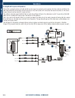
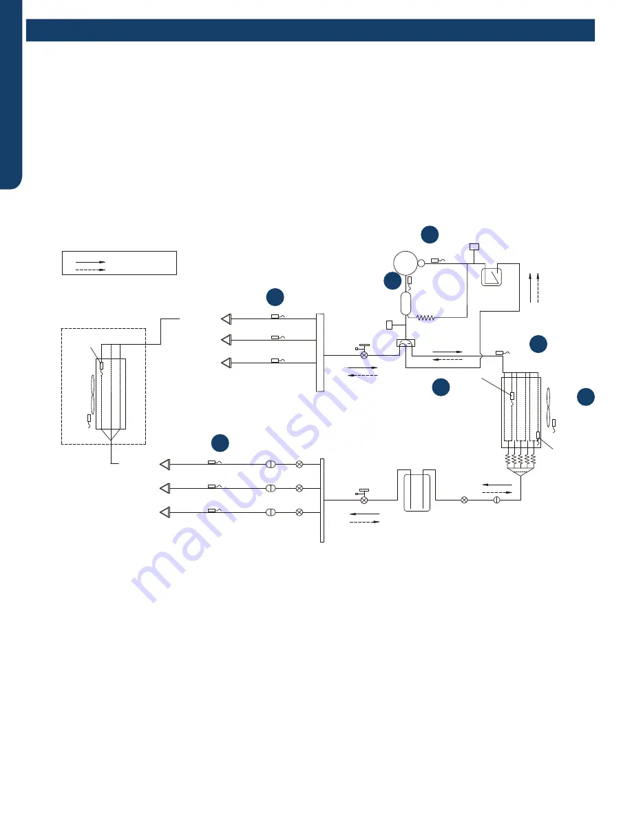
Operations
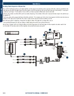
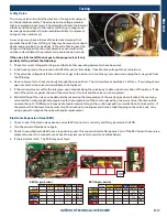
On a call for cooling, the indoor unit will send the room temperature and set-point requirement to the outdoor unit PCB via the
data signal wire path. The data travels from the indoor unit to the outdoor unit via the wire located on terminal 3/C. The indoor
louvers will open and the indoor fan motor will start.
The outdoor unit will energize the EEVs that are controlling refrigerant flow to the calling indoor units. The position of the EEVs
will be set to an initial position based upon the outdoor air temperature.
The 4-way valve is de-energized. After a 3-minute time delay, the outdoor fan motor will be energized. Shortly after the outdoor
fan motor turns on, the compressor will start in low frequency. The operating frequency of the compressor will be displayed on
the Service Monitor Board .
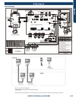
The refrigerant in the system will begin to flow, and the compressor will discharge hot gas into the oil separator. Oil will be
trapped in the separator and returned to the suction inlet of the compressor via the capillary tube assembly low pressure path.
Comp-
ressor
Discharge temp.
●
sensor
Oil
separator
Capillary tube
Ø2.7*Ø1.0*1400
High pressure
switch
4-way valve
Pipe sensor
Toci
Suction temp.
sensor
Ts
Low pressure
switch
Accumulator
Gas
service valve
Outdoor
heat
exchanger
temp.
sensor
FAN-OUT
Outdoor
ambient
temperature
sensor
Ta
Defrost
sensor
Td
Distributor
Strainer
EEV
O
Receiver
Liquid
service valve
5/8
3/8
Unit A liquid pipe temp. sensor
Tc2
Strainer
EEV
A
Indoor unit A
Unit B liquid pipe temp. sensor
Tc2
Strainer
EEV
B
Indoor unit B
Unit C liquid pipe temp. sensor
Tc2
Strainer
EEV
C
Indoor unit C
Unit A gas pipe temp. sensor
Tc1
Unit B gas pipe temp. sensor
Tc1
Unit C gas pipe temp. sensor
Tc1
Indoor unit A
Indoor unit B
Indoor unit C
4-way valve coil:
OFF
ON
Refrigerant flow in cooling
Refrigerant flow in heating
FAN-IN
Indoor
ambient
temperature
sensor
Indoor
heat
exchanger
temp.
sensor
1
2
3
4
7
6
5
Te
Cooling Mode Sequence of Operation
Содержание AB09SC2VHA
Страница 2: ...Oct 2020 Manual release Revision History ...
Страница 12: ... This page intentionally left blank ...
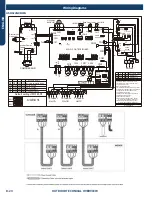
Страница 45: ...WALL MOUNT TECHNICAL OVERVIEW ENGLISH Topic Title C 9 Wiring Diagrams ...
Страница 68: ... This page intentionally left blank ...
Страница 78: ... This page intentionally left blank ...
Страница 104: ... This page intentionally left blank ...