TROUBLESHOOTING & REFERENCES
I-12
ENGLISH
Topic Title
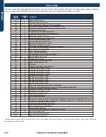
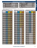
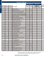
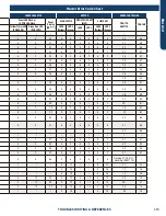
Master Error Code Chart
HIGHWALL CONSOLE
COMPACT CASSETTE
LARGE CASSETTE
DUCTED
WIRED CONTROLLER
Outdoor
Pro-Series
LED Display
(CAC)
Outdoor
Multi-Zone
LED Display
(CAC)
Outdoor
Single-Zone
LED1 Flash
(RAC)
FAULT DESCRIPTION
Digital
Display
Digital
Display
Panel LED Flash or
ID PCB LED Flash
Panel LED Flash or
ID PCB LED Flash
Panel
Display
(PB*****)
HIGH STATIC
MID-STATIC DUCT
(MSP)
SLIM DUCT
YRE-17A
QACT17A
YRE-16B
Yellow Timer LED
(PCB LED5)
Green Run LED
(PCB LED1)
Yellow Timer LED
(PCB LED4)
Green Run LED
(PCB LED1)
LED4
(Yellow)
LED3
(Green)
LED4
LED3
LED4
(Yellow)
LED3
(Green)
1
1
1
Outdoor EEPROM failure
F12
F12
2
1
2
1
15
2
1
2
1
2
1
15
21
2
2
2
IPM overcurrent or short circuit
F1
F1
2
2
2
2
16
2
2
2
2
2
2
16
22
/
/
3
Outdoor alternating current, over current protection
F22
F22
2
3
/
/
/
/
/
/
/
/
/
17
23
3
/
/
Compressor over current during deceleration
/
/
/
/
2
3
17
2
3
2
3
2
3
17
23
4
4
4
Communication failure between the IPM and outdoor PCB
F3
F3
2
4
2
4
18
2
4
2
4
2
4
18
24
5
5
5
Module operated overload (compressor overload protection)
F20*
F20*
2
5
2
5
19
2
5
2
5
2
5
19
25
6
6
6
Module low or high voltage
F19*
F19*
2
6
2
6
1A
2
6
2
6
2
6
1A
26
7
/
7
Compressor current sampling circuit fault
F27
F27
2
7
2
7
1B
2
7
2
7
2
7
1B
27
8
8
8
Overheat protection for discharge temperature
F4
F4
2
8
2
8
1C
2
8
2
8
2
8
1C
28
9
9
9
Malfunction of the DC fan motor
F8*
F8*
2
9
2
9
1D
2
9
2
9
2
9
1D
29
10
10
10
Malfunction of defrost temperature sensor
F21
F21
3
0
3
0
1E
3
0
3
0
3
0
1E
30
11
11
11
Suction temperature sensor failure
F7
F7
3
1
3
1
1F
3
1
3
1
3
1
1F
31
12
12
12
Ambient temperature sensor failure
F6
F6
3
2
3
2
20
3
2
3
2
3
2
20
32
13
13
13
Discharge temperature sensor failure
F25
F25
3
3
3
3
21
3
3
3
3
3
3
21
33
/
/
14
High outdoor suction temperature
F30*
F30*
3
4
/
/
/
/
/
/
/
/
/
22
34
14
/
/
PFC circuit loop voltage
/
/
/
/
3
4
22
3
4
3
4
3
4
22
34
15
15
15
Communication failure between the indoor & outdoor unit
E7
E7
3
5
3
5
23
3
5
3
5
3
5
23
35
16
16
16
Lack of refrigerant or discharging
F13*
F13*
3
6
3
6
24
3
6
3
6
3
6
24
36
17
17
17
4-way valve switching failure
F14*
F14*
3
7
3
7
25
3
7
3
7
3
7
25
37
18
18
18
Loss of synchronism detection
F11
F11
3
8
3
8
26
3
8
3
8
3
8
26
38
/
/
19
Position detection circuit fault of compressor
F28
F28
3
9
/
/
/
/
/
/
/
/
/
27
39
19
/
/
Low DC or AC voltage
/
/
/
/
3
9
27
3
9
3
9
3
9
27
39
/
/
20
Terminal block temp too high
F15*
F15*
4
0
/
/
/
/
/
/
/
/
/
28
40
20
20
/
Indoor thermal overload
E9
/
4
0
4
0
28
4
0
4
0
4
0
28
40
/
21
21
Indoor unit overload protection, heating mode only.
E9*
/
4
1
/
/
/
/
/
/
/
/
/
29
41
/
21
/
Indoor coil frosted
E5
/
4
1
4
1
29
4
1
4
1
4
1
29
41
/
/
22
Indoor anti-frosting protection
E5*
/
4
2
/
/
/
/
/
/
/
/
/
2A
42
22
/
/
PFC circuit loop overcurrent
/
/
/
/
4
2
2A
4
2
4
2
4
2
2A
42
/
/
23
Indoor coil temperature (abnormal reading)
/
/
/
/
/
/
/
/
/
/
/
/
/
/
/
23
23
/
Module thermal overload
F5*
F5*
4
3
4
3
2B
4
3
4
3
4
3
2B
43
24
24
24
Compressor start failure, over-current
F2*
F2*
4
4
4
4
2C
4
4
4
4
4
4
2C
44
25
25
25
Phase current protection (IPM)
F23*
F23
4
5
4
5
2D
4
5
4
5
4
5
2D
45
/
26
/
MCU reset
F9
F9
4
6
4
6
2E
4
6
4
6
4
6
2E
46
26
/
/
IPM power supply phase loss (3-phase)
/
/
/
/
/
2F
47
27
27
27
Module current detect circuit malfunction
F24
F24
4
7
4
7
2F
4
7
4
7
4
7
2F
47
28
/
/
Wiring error: Compressor to IPM
/
/
/
/
/
/
/
/
/
/
/
/
/
/
/
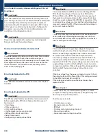
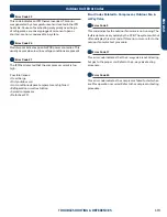
* Hidden indoor error code. LED1 will flash outdoors, but no error will appear on indoor unit display.
To view error code on indoor display, press and hold the Emergency button for 15 seconds.
Содержание AB09SC2VHA
Страница 2: ...Oct 2020 Manual release Revision History ...
Страница 12: ... This page intentionally left blank ...
Страница 45: ...WALL MOUNT TECHNICAL OVERVIEW ENGLISH Topic Title C 9 Wiring Diagrams ...
Страница 68: ... This page intentionally left blank ...
Страница 78: ... This page intentionally left blank ...
Страница 104: ... This page intentionally left blank ...

