


GE Multilin
F35 Multiple Feeder Protection System
3-31
3 HARDWARE
3.3 DIRECT INPUT/OUTPUT COMMUNICATIONS
3
6.
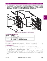
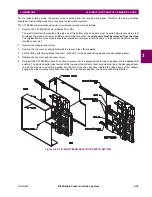
Re-insert the G.703 module. Take care to ensure that the
correct
module type is inserted into the
correct
slot position.
The ejector/inserter clips located at the top and at the bottom of each module must be in the disengaged position as
the module is smoothly inserted into the slot. Once the clips have cleared the raised edge of the chassis, engage the
clips simultaneously. When the clips have locked into position, the module will be fully inserted.
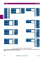
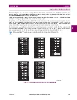
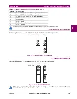
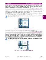
Figure 3–35: G.703 TIMING SELECTION SWITCH SETTING
c) G.703 OCTET TIMING
If octet timing is enabled (on), this 8 kHz signal will be asserted during the violation of bit 8 (LSB) necessary for connecting
to higher order systems. When F35s are connected back to back, octet timing should be disabled (off).
d) G.703 TIMING MODES
There are two timing modes for the G.703 module: internal timing mode and loop timing mode (default).
•
Internal Timing Mode:
The system clock is generated internally. Therefore, the G.703 timing selection should be in
the internal timing mode for back-to-back (UR-to-UR) connections. For back-to-back connections, set for octet timing
(S1 = OFF) and timing mode to internal timing (S5 = ON and S6 = OFF).
•
Loop Timing Mode:
The system clock is derived from the received line signal. Therefore, the G.703 timing selection
should be in loop timing mode for connections to higher order systems. For connection to a higher order system (UR-
to-multiplexer, factory defaults), set to octet timing (S1 = ON) and set timing mode to loop timing (S5 = OFF and S6 =
OFF).
Table 3–5: G.703 TIMING SELECTIONS
SWITCHES
FUNCTION
S1
OFF
→
octet timing disabled
ON
→
octet timing 8 kHz
S5 and S6
S5 = OFF and S6 = OFF
→
loop timing mode
S5 = ON and S6 = OFF
→
internal timing mode
S5 = OFF and S6 = ON
→
minimum remote loopback mode
S5 = ON and S6 = ON
→
dual loopback mode
Содержание F35
Страница 2: ......
Страница 4: ......
Страница 30: ...1 20 F35 Multiple Feeder Protection System GE Multilin 1 5 USING THE RELAY 1 GETTING STARTED 1 ...
Страница 122: ...4 30 F35 Multiple Feeder Protection System GE Multilin 4 3 FACEPLATE INTERFACE 4 HUMAN INTERFACES 4 ...
Страница 296: ...5 174 F35 Multiple Feeder Protection System GE Multilin 5 9 TESTING 5 SETTINGS 5 ...
Страница 328: ...7 8 F35 Multiple Feeder Protection System GE Multilin 7 2 TARGETS 7 COMMANDS AND TARGETS 7 ...
Страница 332: ...8 4 F35 Multiple Feeder Protection System GE Multilin 8 1 FAULT LOCATOR 8 THEORY OF OPERATION 8 ...
Страница 350: ...A 16 F35 Multiple Feeder Protection System GE Multilin A 1 PARAMETER LIST APPENDIXA A ...
Страница 422: ...B 72 F35 Multiple Feeder Protection System GE Multilin B 4 MEMORY MAPPING APPENDIXB B ...
Страница 460: ...D 10 F35 Multiple Feeder Protection System GE Multilin D 1 IEC 60870 5 104 PROTOCOL APPENDIXD D ...
Страница 472: ...E 12 F35 Multiple Feeder Protection System GE Multilin E 2 DNP POINT LISTS APPENDIXE E ...