


5-88
F35 Multiple Feeder Protection System
GE Multilin
5.4 FLEXLOGIC™
5 SETTINGS
5
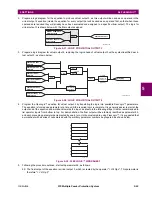
ELEMENT:
Disturbance
detector
SRC1 50DD OP
SRC2 50DD OP
SRC3 50DD OP
SRC4 50DD OP
SRC5 50DD OP
SRC6 50DD OP
Source 1 disturbance detector has operated
Source 2 disturbance detector has operated
Source 3 disturbance detector has operated
Source 4 disturbance detector has operated
Source 5 disturbance detector has operated
Source 6 disturbance detector has operated
ELEMENT:
Disconnect switch
SWITCH 1 OFF CMD
SWITCH 1 ON CMD
SWITCH 1
Φ
A BAD ST
SWITCH 1
Φ
A INTERM
SWITCH 1
Φ
A CLSD
SWITCH 1
Φ
A OPEN
SWITCH 1
Φ
B BAD ST
SWITCH 1
Φ
B INTERM
SWITCH 1
Φ
B CLSD
SWITCH 1
Φ
B OPEN
SWITCH 1
Φ
C BAD ST
SWITCH 1
Φ
C INTERM
SWITCH 1
Φ
C CLSD
SWITCH 1
Φ
C OPEN
SWITCH 1 BAD STATUS
SWITCH 1 CLOSED
SWITCH 1 OPEN
SWITCH 1 DISCREP
SWITCH 1 TROUBLE
Disconnect switch 1 open command initiated
Disconnect switch 1 close command initiated
Disconnect switch 1 phase A bad status is detected (discrepancy between
the 52/a and 52/b contacts)
Disconnect switch 1 phase A intermediate status is detected (transition from
one position to another)
Disconnect switch 1 phase A is closed
Disconnect switch 1 phase A is open
Disconnect switch 1 phase B bad status is detected (discrepancy between
the 52/a and 52/b contacts)
Disconnect switch 1 phase A intermediate status is detected (transition from
one position to another)
Disconnect switch 1 phase B is closed
Disconnect switch 1 phase B is open
Disconnect switch 1 phase C bad status is detected (discrepancy between
the 52/a and 52/b contacts)
Disconnect switch 1 phase A intermediate status is detected (transition from
one position to another)
Disconnect switch 1 phase C is closed
Disconnect switch 1 phase C is open
Disconnect switch 1 bad status is detected on any pole
Disconnect switch 1 is closed
Disconnect switch 1 is open
Disconnect switch 1 has discrepancy
Disconnect switch 1 trouble alarm
SWITCH 2...
Same set of operands as shown for SWITCH 1
ELEMENT:
Teleprotection
channel tests
TELEPRO CH1 FAIL
TELEPRO CH2 FAIL
TELEPRO CH1 ID FAIL
TELEPRO CH2 ID FAIL
TELEPRO CH1 CRC FAIL
TELEPRO CH2 CRC FAIL
TELEPRO CH1 PKT LOST
TELEPRO CH2 PKT LOST
Channel 1 failed
Channel 2 failed
The ID check for a peer relay on channel 1 has failed
The ID check for a peer relay on channel 2 has failed
CRC detected packet corruption on channel 1
CRC detected packet corruption on channel 2
CRC detected lost packet on channel 1
CRC detected lost packet on channel 2
ELEMENT:
Teleprotection
inputs/outputs
TELEPRO INPUT 1-1 On
↓
TELEPRO INPUT 1-16 On
TELEPRO INPUT 2-1 On
↓
TELEPRO INPUT 2-16 On
Flag is set, Logic =1
↓
Flag is set, Logic =1
Flag is set, Logic =1
↓
Flag is set, Logic =1
ELEMENT
Trip bus
TRIP BUS 1 PKP
TRIP BUS 1 OP
Asserted when the trip bus 1 element picks up.
Asserted when the trip bus 1 element operates.
TRIP BUS 2...
Same set of operands as shown for TRIP BUS 1
ELEMENT:
Underfrequency
UNDERFREQ 1 PKP
UNDERFREQ 1 OP
UNDERFREQ 1 DPO
Underfrequency 1 has picked up
Underfrequency 1 has operated
Underfrequency 1 has dropped out
UNDERFREQ 2 to 6
Same set of operands as shown for UNDERFREQ 1 above
FIXED OPERANDS
Off
Logic = 0. Does nothing and may be used as a delimiter in an equation list;
used as ‘Disable’ by other features.
On
Logic = 1. Can be used as a test setting.
INPUTS/OUTPUTS:
Contact inputs
Cont Ip 1
On
Cont Ip 2
On
↓
Cont Ip 1
Off
Cont Ip 2
Off
↓
(will not appear unless ordered)
(will not appear unless ordered)
↓
(will not appear unless ordered)
(will not appear unless ordered)
↓
INPUTS/OUTPUTS:
Contact outputs,
current
(from detector on
form-A output only)
Cont Op 1
IOn
Cont Op 2
IOn
↓
(will not appear unless ordered)
(will not appear unless ordered)
↓
Cont Op 1
IOff
Cont Op 2
IOff
↓
(will not appear unless ordered)
(will not appear unless ordered)
↓
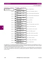
Table 5–7: F35 FLEXLOGIC™ OPERANDS (Sheet 4 of 6)
OPERAND TYPE
OPERAND SYNTAX
OPERAND DESCRIPTION
Содержание F35
Страница 2: ......
Страница 4: ......
Страница 30: ...1 20 F35 Multiple Feeder Protection System GE Multilin 1 5 USING THE RELAY 1 GETTING STARTED 1 ...
Страница 122: ...4 30 F35 Multiple Feeder Protection System GE Multilin 4 3 FACEPLATE INTERFACE 4 HUMAN INTERFACES 4 ...
Страница 296: ...5 174 F35 Multiple Feeder Protection System GE Multilin 5 9 TESTING 5 SETTINGS 5 ...
Страница 328: ...7 8 F35 Multiple Feeder Protection System GE Multilin 7 2 TARGETS 7 COMMANDS AND TARGETS 7 ...
Страница 332: ...8 4 F35 Multiple Feeder Protection System GE Multilin 8 1 FAULT LOCATOR 8 THEORY OF OPERATION 8 ...
Страница 350: ...A 16 F35 Multiple Feeder Protection System GE Multilin A 1 PARAMETER LIST APPENDIXA A ...
Страница 422: ...B 72 F35 Multiple Feeder Protection System GE Multilin B 4 MEMORY MAPPING APPENDIXB B ...
Страница 460: ...D 10 F35 Multiple Feeder Protection System GE Multilin D 1 IEC 60870 5 104 PROTOCOL APPENDIXD D ...
Страница 472: ...E 12 F35 Multiple Feeder Protection System GE Multilin E 2 DNP POINT LISTS APPENDIXE E ...