4-16
F35 Multiple Feeder Protection System
GE Multilin
4.3 FACEPLATE INTERFACE
4 HUMAN INTERFACES
4
•
TRIP
:
Indicates that the selected FlexLogic™ operand serving as a Trip switch has operated. This indicator always
latches; the reset command must be initiated to allow the latch to be reset.
•
ALARM
:
Indicates that the selected FlexLogic™ operand serving as an Alarm switch has operated. This indicator is
never latched.
•
PICKUP
:
Indicates that an element is picked up. This indicator is never latched.
EVENT CAUSE INDICATORS:
These indicate the input type that was involved in a condition detected by an element that is operated or has a latched flag
waiting to be reset.
•
VOLTAGE
: Indicates voltage was involved.
•
CURRENT
: Indicates current was involved.
•
FREQUENCY
: Indicates frequency was involved.
•
OTHER
: Indicates a composite function was involved.
•
PHASE A
: Indicates phase A was involved.
•
PHASE B
: Indicates phase B was involved.
•
PHASE C
: Indicates phase C was involved.
•
NEUTRAL/GROUND
: Indicates that neutral or ground was involved.
USER-PROGRAMMABLE INDICATORS:
The second and third provide 48 amber LED indicators whose operation is controlled by the user. Support for applying a
customized label beside every LED is provided.
User customization of LED operation is of maximum benefit in installations where languages other than English are used to
communicate with operators. Refer to the
User-programmable LEDs
section in chapter 5 for the settings used to program
the operation of the LEDs on these panels.
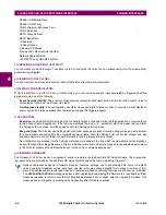
Figure 4–20: LED PANELS 2 AND 3 (INDEX TEMPLATE)
DEFAULT LABELS FOR LED PANEL 2:
The default labels are intended to represent:
•
GROUP 1...6
: The illuminated GROUP is the active settings group.
•
RECLOSE ENABLED
: The recloser is operational.
•
RECLOSE DISABLED
: The recloser is not operational.
•
RECLOSE IN PROGRESS
: A reclose operation is in progress.
•
RECLOSE LOCKED OUT
: The recloser is not operational and requires a reset.
Firmware revisions 2.9x and earlier support eight user setting groups; revisions 3.0x and higher support
six setting groups. For convenience of users using earlier firmware revisions, the relay panel shows eight
setting groups. Please note that the LEDs, despite their default labels, are fully user-programmable.
USER-PROGRAMMABLE LEDS
USER-PROGRAMMABLE LEDS
842782A1.CDR
NOTE
Содержание F35
Страница 2: ......
Страница 4: ......
Страница 30: ...1 20 F35 Multiple Feeder Protection System GE Multilin 1 5 USING THE RELAY 1 GETTING STARTED 1 ...
Страница 122: ...4 30 F35 Multiple Feeder Protection System GE Multilin 4 3 FACEPLATE INTERFACE 4 HUMAN INTERFACES 4 ...
Страница 296: ...5 174 F35 Multiple Feeder Protection System GE Multilin 5 9 TESTING 5 SETTINGS 5 ...
Страница 328: ...7 8 F35 Multiple Feeder Protection System GE Multilin 7 2 TARGETS 7 COMMANDS AND TARGETS 7 ...
Страница 332: ...8 4 F35 Multiple Feeder Protection System GE Multilin 8 1 FAULT LOCATOR 8 THEORY OF OPERATION 8 ...
Страница 350: ...A 16 F35 Multiple Feeder Protection System GE Multilin A 1 PARAMETER LIST APPENDIXA A ...
Страница 422: ...B 72 F35 Multiple Feeder Protection System GE Multilin B 4 MEMORY MAPPING APPENDIXB B ...
Страница 460: ...D 10 F35 Multiple Feeder Protection System GE Multilin D 1 IEC 60870 5 104 PROTOCOL APPENDIXD D ...
Страница 472: ...E 12 F35 Multiple Feeder Protection System GE Multilin E 2 DNP POINT LISTS APPENDIXE E ...

