


GE Multilin
F35 Multiple Feeder Protection System
5-161
5 SETTINGS
5.7 INPUTS/OUTPUTS
5
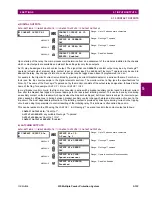
Assume that Phase Instantaneous Overcurrent 1 is used by Devices 2, 3, and 4 to block Device 1. If not blocked, Device 1
would trip the bus upon detecting a fault and applying a short coordination time delay.
The following settings should be applied (assume Bit 3 is used by all 3 devices to sent the blocking signal and Direct Inputs
7, 8, and 9 are used by the receiving device to monitor the three blocking signals):
UR IED 2:
DIRECT OUT 3 OPERAND
: "
PHASE IOC1 OP
"
UR IED 3:
DIRECT OUT 3 OPERAND
: "
PHASE IOC1 OP
"
UR IED 4:
DIRECT OUT 3 OPERAND
: "
PHASE IOC1 OP
"
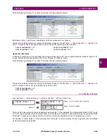
UR IED 1:
DIRECT INPUT 7 DEVICE ID
: "2"
DIRECT INPUT 7 BIT NUMBER
: "3"
DIRECT INPUT 7 DEFAULT STATE
: select "On" for security, select "Off" for dependability
DIRECT INPUT 8 DEVICE ID
: "3"
DIRECT INPUT 8 BIT NUMBER
: "3"
DIRECT INPUT 8 DEFAULT STATE
: select "On" for security, select "Off" for dependability
DIRECT INPUT 9 DEVICE ID
: "4"
DIRECT INPUT 9 BIT NUMBER
: "3"
DIRECT INPUT 9 DEFAULT STATE
: select "On" for security, select "Off" for dependability
Now the three blocking signals are available in UR IED 1 as
DIRECT INPUT 7 ON
,
DIRECT INPUT 8 ON
, and
DIRECT INPUT 9
ON
. Upon losing communications or a device, the scheme is inclined to block (if any default state is set to “On”), or to trip
the bus on any overcurrent condition (all default states set to “Off”).
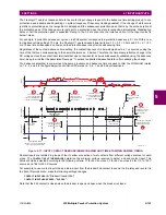
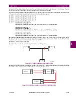
EXAMPLE 2: PILOT-AIDED SCHEMES
Consider a three-terminal line protection application shown in the figure below.
Figure 5–81: THREE-TERMINAL LINE APPLICATION
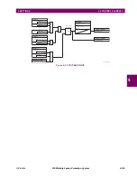
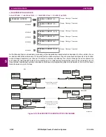
Assume the Hybrid Permissive Overreaching Transfer Trip (Hybrid POTT) scheme is applied using the architecture shown
below. The scheme output operand
HYB POTT TX1
is used to key the permission.
Figure 5–82: SINGLE-CHANNEL OPEN-LOOP CONFIGURATION
842713A1.CDR
UR IED 1
UR IED 2
UR IED 3
842714A1.CDR
UR IED 1
TX1
RX1
UR IED 2
RX2
TX2
RX1
TX1
UR IED 3
RX1
TX1
Содержание F35
Страница 2: ......
Страница 4: ......
Страница 30: ...1 20 F35 Multiple Feeder Protection System GE Multilin 1 5 USING THE RELAY 1 GETTING STARTED 1 ...
Страница 122: ...4 30 F35 Multiple Feeder Protection System GE Multilin 4 3 FACEPLATE INTERFACE 4 HUMAN INTERFACES 4 ...
Страница 296: ...5 174 F35 Multiple Feeder Protection System GE Multilin 5 9 TESTING 5 SETTINGS 5 ...
Страница 328: ...7 8 F35 Multiple Feeder Protection System GE Multilin 7 2 TARGETS 7 COMMANDS AND TARGETS 7 ...
Страница 332: ...8 4 F35 Multiple Feeder Protection System GE Multilin 8 1 FAULT LOCATOR 8 THEORY OF OPERATION 8 ...
Страница 350: ...A 16 F35 Multiple Feeder Protection System GE Multilin A 1 PARAMETER LIST APPENDIXA A ...
Страница 422: ...B 72 F35 Multiple Feeder Protection System GE Multilin B 4 MEMORY MAPPING APPENDIXB B ...
Страница 460: ...D 10 F35 Multiple Feeder Protection System GE Multilin D 1 IEC 60870 5 104 PROTOCOL APPENDIXD D ...
Страница 472: ...E 12 F35 Multiple Feeder Protection System GE Multilin E 2 DNP POINT LISTS APPENDIXE E ...