70
www.gateway.com
6
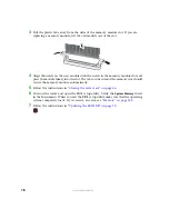
Hold the sixth drive option board above and in front of the opening in the backplane.
7
Align the tabs in the option board with the holes in the backplane, then move the
board down and toward the back of the chassis to seat the board.
Make sure the bottom of the option board seats into the plastic retainer at the bottom
of the opening in the backplane.
8
Connect the end of the long SCSI cable labeled “Backplane” to the connector on the
sixth drive option board labeled “M/B,” then connect the remaining end of the cable
to the SCSI connector on the system board or SCSI add-in card.
9
Connect one end of the short SCSI cable labeled “Backplane” to the backplane
connector labeled “SCSI CH A,” then connect the other end to the sixth drive option
board SCSI connector on the back of the board.
10
Using the power cable labeled “Drive 5 Pwer” (included with the sixth drive option
kit), connect one end to the “OPT” connector on the sixth drive option board and
the other end to the “OPT END” connector on the backplane. See
for connector locations.
11
Reinstall the fan module by following the instructions in
.
12
Follow the instructions in
Содержание 9515
Страница 1: ...User Guide Gateway 9515 Server ...
Страница 5: ...iv www gateway com B BIOS Settings 155 C Safety Regulatory and Legal Information 173 Index 181 ...
Страница 15: ...10 www gateway com ...
Страница 125: ...120 www gateway com ...
Страница 151: ...146 www gateway com ...
Страница 177: ...172 www gateway com ...
Страница 178: ...Appendix C 173 Safety Regulatory and Legal Information Safety information Legal and Regulatory Information ...
Страница 193: ...188 www gateway com ...
Страница 194: ...A MAN 9515 USR GDE R0 12 04 ...


