106
www.gateway.com
4
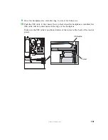
Press the blue latch at the back of the control panel module, then slide the module
out of the chassis enough to reach the USB and front panel cables.
5
Disconnect the USB and front panel connectors from the control panel module, then
remove the control panel from the chassis.
6
Slide the new control panel module into the chassis far enough to let you connect
the USB and front panel cables.
7
Connect the USB and front panel cables to the control panel module, then slide the
module into the chassis until it clicks into place.
8
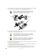
If you disconnected the USB and front panel cables from the system board or
backplane when you removed the control panel module, reconnect the cables.
Important
You may need to disconnect the USB and front panel cables from
the system board or backplane to provide sufficient slack in the cables
to gain access to the control panel cable connectors.
Caution
The USB header has a latch to hold the connector on. Be careful to
unlatch the USB connector when removing it from the control panel
or you could damage the connector or the header.
Important
The position of the USB connector is different in the standard control
panel than in the optional local control panel. Note the positions of
the cable connectors as you remove them from the module.
Latch
Front panel
cable
USB cable
Содержание 9515
Страница 1: ...User Guide Gateway 9515 Server ...
Страница 5: ...iv www gateway com B BIOS Settings 155 C Safety Regulatory and Legal Information 173 Index 181 ...
Страница 15: ...10 www gateway com ...
Страница 125: ...120 www gateway com ...
Страница 151: ...146 www gateway com ...
Страница 177: ...172 www gateway com ...
Страница 178: ...Appendix C 173 Safety Regulatory and Legal Information Safety information Legal and Regulatory Information ...
Страница 193: ...188 www gateway com ...
Страница 194: ...A MAN 9515 USR GDE R0 12 04 ...

