Page 2-10
500W Series Installation Manual
Rev. D
190-00357-02
NOTE
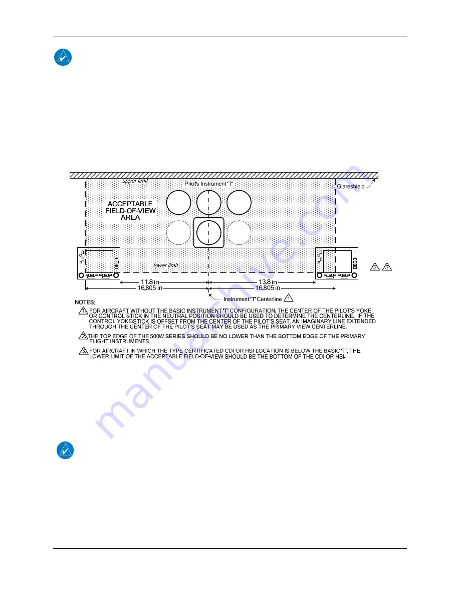
The entire annunciator must be within 16.805 inches of the view centerline.
The external GPS Navigation annunciator unit must contain, at a minimum, the following annunciations:
•
INTEG, INTG or LOI
•
TERM
•
APR
•
MSG
•
WPT
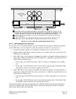
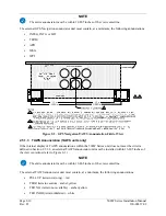
Figure 2-3. GPS Navigation/TAWS Annunciation Field of View
2.5.1.3 TAWS Annunciation (TAWS units only)
If the internal display of TAWS annunciations within the 500W Series unit does not meet the criteria
defined in Section 2.5.1.2, an external TAWS annunciator unit must be installed within 16.805 inches of
the view centerline (refer to Figure 2-3).
NOTE
The entire annunciator must be within 16.805 inches of the view centerline.
The external TAWS annunciator unit must contain, at a minimum, the following annunciations.
•
PULL UP (terrain warning) – red
•
TERR (terrain caution) – amber/yellow
•
TER N/A (terrain not available) – amber/yellow
•
TER INHB (terrain inhibited) – white
Содержание GNS 530W
Страница 2: ...500W Series Installation Manual 190 00357 02 Rev D...
Страница 12: ...Page viii 500W Series Installation Manual Rev D 190 00357 02 This Page Intentionally Left Blank...
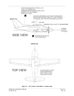
Страница 33: ...500W Series Installation Manual Page 2 5 190 00357 02 Rev D Figure 2 1 GPS Antenna Installation Considerations...
Страница 40: ...Page 2 12 500W Series Installation Manual Rev D 190 00357 02 This Page Intentionally Left Blank...
Страница 122: ...Page 5 44 500W Series Installation Manual Rev D 190 00357 02 This Page Intentionally Left Blank...
Страница 130: ...Page 7 4 500W Series Installation Manual Rev D 190 00357 02 This Page Intentionally Left Blank...
Страница 132: ...Page 8 2 500W Series Installation Manual Rev D 190 00357 02 This Page Intentionally Left Blank...
Страница 134: ...Page A 2 500W Series Installation Manual Rev D 190 00357 02 This Page Intentionally Left Blank...
Страница 136: ...Page B 2 500W Series Installation Manual Rev D 190 00357 02 This Page Intentionally Left Blank...
Страница 137: ...500W Series Installation Manual Page C 1 190 00357 02 Rev D Appendix C RESERVED...
Страница 138: ...Page C 2 500W Series Installation Manual Rev D 190 00357 02 This Page Intentionally Left Blank...
Страница 148: ...Page E 6 500W Series Installation Manual Rev D 190 00357 02 This Page Intentionally Left Blank...
Страница 150: ...Page F 2 500W Series Installation Manual Rev D 190 00357 02 This Page Intentionally Left Blank...
Страница 160: ...Page G 6 500W Series Installation Manual Rev D 190 00357 02 This Page Intentionally Left Blank...
Страница 162: ...Page H 2 500W Series Installation Manual Rev D 190 00357 02 This Page Intentionally Left Blank...
Страница 163: ...500W Series Installation Manual Page H 3 190 00357 02 Rev D Figure H 1 500W Series Unit System Interface Diagram...
Страница 164: ...Page H 4 500W Series Installation Manual Rev D 190 00357 02 Figure H 2 GNS 530W Typical Installation Sheet 1 of 2...
Страница 165: ...500W Series Installation Manual Page H 5 190 00357 02 Rev D Figure H 2 GNS 530W Typical Installation Sheet 2 of 2...
Страница 166: ...Page H 6 500W Series Installation Manual Rev D 190 00357 02 Figure H 3 GPS 500W Typical Installation Sheet 1 of 2...
Страница 167: ...500W Series Installation Manual Page H 7 190 00357 02 Rev D Figure H 3 GPS 500W Typical Installation Sheet 2 of 2...
Страница 172: ...Page H 12 500W Series Installation Manual Rev D 190 00357 02 Figure H 6 Main Indicator Interconnect...
Страница 173: ...500W Series Installation Manual Page H 13 190 00357 02 Rev D Figure H 7 KI 209A Main Indicator Interconnect...
Страница 174: ...Page H 14 500W Series Installation Manual Rev D 190 00357 02 Figure H 8 KI 208A Main Indicator Interconnect...
Страница 175: ...500W Series Installation Manual Page H 15 190 00357 02 Rev D Figure H 9 RS 232 Serial Data Interconnect Sheet 1 of 2...
Страница 176: ...Page H 16 500W Series Installation Manual Rev D 190 00357 02 Figure H 9 RS 232 Serial Data Interconnect Sheet 2 of 2...
Страница 177: ...500W Series Installation Manual Page H 17 190 00357 02 Rev D Figure H 10 ARINC 429 EFIS Interconnect Sheet 1 of 2...
Страница 178: ...Page H 18 500W Series Installation Manual Rev D 190 00357 02 Figure H 10 ARINC 429 EFIS Interconnect Sheet 2 of 2...
Страница 188: ...Page H 28 500W Series Installation Manual Rev D 190 00357 02 Figure H 16 GTX 330 Interconnect...
Страница 189: ...500W Series Installation Manual Page H 29 190 00357 02 Rev D Figure H 17 Weather and Terrain Interconnect Sheet 1 of 2...
Страница 190: ...Page H 30 500W Series Installation Manual Rev D 190 00357 02 Figure H 17 Weather and Terrain Interconnect Sheet 2 of 2...
Страница 191: ...500W Series Installation Manual Page H 31 190 00357 02 Rev D Figure H 18 Audio Panel Interconnect Sheet 1 of 2...
Страница 192: ...Page H 32 500W Series Installation Manual Rev D 190 00357 02 Figure H 18 Audio Panel Interconnect Sheet 2 of 2...
Страница 193: ...500W Series Installation Manual Page H 33 190 00357 02 Rev D Figure H 19 VOR ILS Indicator Interconnect...
Страница 194: ...Page H 34 500W Series Installation Manual Rev D 190 00357 02 Figure H 20 RMI OBI Interconnect...
Страница 195: ...500W Series Installation Manual Page H 35 190 00357 02 Rev D Figure H 21 King Serial Panel DME Tuning Interconnect...
Страница 196: ...Page H 36 500W Series Installation Manual Rev D 190 00357 02 Figure H 22 King Serial Remote DME Tuning Interconnect...
Страница 197: ...500W Series Installation Manual Page H 37 190 00357 02 Rev D Figure H 23 Parallel 2 of 5 DME Tuning Interconnect...
Страница 198: ...Page H 38 500W Series Installation Manual Rev D 190 00357 02 Figure H 24 TAWS Interconnect...
Страница 199: ...500W Series Installation Manual Page H 39 190 00357 02 Rev D Figure H 25 Bendix King Analog Autopilot Interconnect...
Страница 200: ...Page H 40 500W Series Installation Manual Rev D 190 00357 02 Figure H 26 Century Autopilot Interconnect Sheet 1 of 2...
Страница 201: ...500W Series Installation Manual Page H 41 190 00357 02 Rev D H 26 Century Autopilot Interconnect Sheet 2 of 2...
Страница 202: ...Page H 42 500W Series Installation Manual Rev D 190 00357 02 Figure H 27 S TEC Autopilot Interconnect Sheet 1 of 2...
Страница 203: ...500W Series Installation Manual Page H 43 190 00357 02 Rev D Figure H 27 S TEC Autopilot Interconnect Sheet 2 of 2...
Страница 208: ...Page H 48 500W Series Installation Manual Rev D 190 00357 02 Figure H 30 Parallel Slip Code DME Tuning Interconnect...
Страница 209: ...500W Series Installation Manual Page H 49 190 00357 02 Rev D Figure H 31 Cessna Autopilot Interconnect...
Страница 210: ...Page H 50 500W Series Installation Manual Rev D 190 00357 02 Figure H 32 Bendix Autopilot Interconnect...
Страница 211: ...500W Series Installation Manual Page H 51 190 00357 02 Rev D Figure H 33 Switches Interconnect...
Страница 214: ...Page H 54 500W Series Installation Manual Rev D 190 00357 02 This Page Intentionally Left Blank...
Страница 215: ......
Страница 216: ......

