Page 1-2
500W Series Installation Manual
Rev. D
190-00357-02
1.2 Scope
The installation instructions and other data contained within this manual are FAA approved under
400W/500W Series AML STC SA01933LA, which is applicable for implementation within airplanes
that are type certificated only under Civil Air Regulation 3 (CAR 3) or 14 Code of Federal Regulations
(CFR) Part 23 (only) into which the Garmin 500W Series unit equipment is qualified for installation and
operational approval. Only the equipment and systems interfaces described in this manual have been
determined to be mutually compatible and are operationally suitable and approved for use as
characterized herein, or within the FAA approved airplane flight manual supplement (AFMS) reflecting
main software version 2.00 and later. Some differences in operation may be observed when comparing
the information in this manual and the FAA approved AFMS to later FAA approved software versions.
Such differences will be identified in revised editions of the FAA approved AFMS characterizing later
software versions, and any applicable limitations and normal or abnormal operating conditions.
It is possible for installers and other appropriately certificated persons to seek FAA approval for
installation and operational use of the 500W Series equipment with systems not identified in this manual,
such as for aircraft certificated under 14 CFR parts 25, 27, or 29, by means of a field approval, STC or
TC. Refer to FAA Advisory Circular (AC) 20-138A and other applicable guidance when applying for
installation and operational approval. AC 21-40 provides guidance for the STC approval process and AC
43-210 provides guidance for the field approval process. If the field approval process is used, it is
advisable to consider the conditions and stipulations in FAA Flight Standards Flight Standards
Information Bulletin for Airworthiness (FSAW), 94-32, “Guidance for Performing Field Approvals of
Installation and Operational Use of Global Positioning Systems (GPS) or GPS with Wide Area
Augmentation Systems (GPS/WAAS), Referred to as Global Navigation Satellite Systems (GNSS)
Equipment”, as revised.
Regardless of applicability of the AML STC or alternative application for installation and operational
approval, prior to completing the installation and before returning the airplane to service, the installer or
other appropriately certificated person is required to complete and submit an FAA Form 337 (OMB No.
2120-0020), “Major Repair and Alteration Airframe, Powerplant, Propeller, or Appliance” to their local
FAA Flight Standards District Office describing the work accomplished. The FAA Form 337 must detail
the equipment and systems to which the respective GPS 500W, GNS 530W, or GNS 530AW is
interfaced and reflect appropriately approved or acceptable data for which follow-on FAA field approval
is being sought. See AC 43.9-1E for instructions for completing the FAA Form 337.
1.3 Equipment
Description
The 500W Series units are 6.25 inches wide and 4.60 inches high. The display is a 320 by 234 pixel
color LCD. The units include two removable data cards, one with a Jeppesen database (to be inserted in
the left most card slot), and the second being a TAWS/TERRAIN database (to be inserted in the right
most card slot).
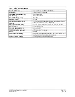
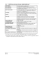
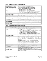
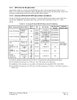
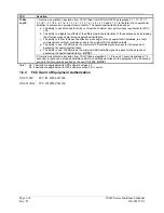
The GPS 500W is a GPS/WAAS unit that meets the requirements of Technical Standard Order (TSO)-
C146a (specified in Table 1-4) and may be approved for IFR en route, terminal, non-precision, and
precision approach operations when installed in reference to the instructions in this manual as referenced
in the AML STC SA01933LA.
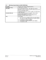
The GNS 530W includes all the features of the GPS 500W and also includes an airborne VHF
communications transceiver and airborne VOR/localizer (LOC) and glideslope (G/S) receivers. The
“AW” model is a 28 VDC unit with a 16 Watt COM transmitter. The GNS 530W/(AW) meets the
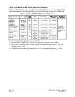
requirements of TSOs specified in Table 1-4.
Содержание GNS 530W
Страница 2: ...500W Series Installation Manual 190 00357 02 Rev D...
Страница 12: ...Page viii 500W Series Installation Manual Rev D 190 00357 02 This Page Intentionally Left Blank...
Страница 33: ...500W Series Installation Manual Page 2 5 190 00357 02 Rev D Figure 2 1 GPS Antenna Installation Considerations...
Страница 40: ...Page 2 12 500W Series Installation Manual Rev D 190 00357 02 This Page Intentionally Left Blank...
Страница 122: ...Page 5 44 500W Series Installation Manual Rev D 190 00357 02 This Page Intentionally Left Blank...
Страница 130: ...Page 7 4 500W Series Installation Manual Rev D 190 00357 02 This Page Intentionally Left Blank...
Страница 132: ...Page 8 2 500W Series Installation Manual Rev D 190 00357 02 This Page Intentionally Left Blank...
Страница 134: ...Page A 2 500W Series Installation Manual Rev D 190 00357 02 This Page Intentionally Left Blank...
Страница 136: ...Page B 2 500W Series Installation Manual Rev D 190 00357 02 This Page Intentionally Left Blank...
Страница 137: ...500W Series Installation Manual Page C 1 190 00357 02 Rev D Appendix C RESERVED...
Страница 138: ...Page C 2 500W Series Installation Manual Rev D 190 00357 02 This Page Intentionally Left Blank...
Страница 148: ...Page E 6 500W Series Installation Manual Rev D 190 00357 02 This Page Intentionally Left Blank...
Страница 150: ...Page F 2 500W Series Installation Manual Rev D 190 00357 02 This Page Intentionally Left Blank...
Страница 160: ...Page G 6 500W Series Installation Manual Rev D 190 00357 02 This Page Intentionally Left Blank...
Страница 162: ...Page H 2 500W Series Installation Manual Rev D 190 00357 02 This Page Intentionally Left Blank...
Страница 163: ...500W Series Installation Manual Page H 3 190 00357 02 Rev D Figure H 1 500W Series Unit System Interface Diagram...
Страница 164: ...Page H 4 500W Series Installation Manual Rev D 190 00357 02 Figure H 2 GNS 530W Typical Installation Sheet 1 of 2...
Страница 165: ...500W Series Installation Manual Page H 5 190 00357 02 Rev D Figure H 2 GNS 530W Typical Installation Sheet 2 of 2...
Страница 166: ...Page H 6 500W Series Installation Manual Rev D 190 00357 02 Figure H 3 GPS 500W Typical Installation Sheet 1 of 2...
Страница 167: ...500W Series Installation Manual Page H 7 190 00357 02 Rev D Figure H 3 GPS 500W Typical Installation Sheet 2 of 2...
Страница 172: ...Page H 12 500W Series Installation Manual Rev D 190 00357 02 Figure H 6 Main Indicator Interconnect...
Страница 173: ...500W Series Installation Manual Page H 13 190 00357 02 Rev D Figure H 7 KI 209A Main Indicator Interconnect...
Страница 174: ...Page H 14 500W Series Installation Manual Rev D 190 00357 02 Figure H 8 KI 208A Main Indicator Interconnect...
Страница 175: ...500W Series Installation Manual Page H 15 190 00357 02 Rev D Figure H 9 RS 232 Serial Data Interconnect Sheet 1 of 2...
Страница 176: ...Page H 16 500W Series Installation Manual Rev D 190 00357 02 Figure H 9 RS 232 Serial Data Interconnect Sheet 2 of 2...
Страница 177: ...500W Series Installation Manual Page H 17 190 00357 02 Rev D Figure H 10 ARINC 429 EFIS Interconnect Sheet 1 of 2...
Страница 178: ...Page H 18 500W Series Installation Manual Rev D 190 00357 02 Figure H 10 ARINC 429 EFIS Interconnect Sheet 2 of 2...
Страница 188: ...Page H 28 500W Series Installation Manual Rev D 190 00357 02 Figure H 16 GTX 330 Interconnect...
Страница 189: ...500W Series Installation Manual Page H 29 190 00357 02 Rev D Figure H 17 Weather and Terrain Interconnect Sheet 1 of 2...
Страница 190: ...Page H 30 500W Series Installation Manual Rev D 190 00357 02 Figure H 17 Weather and Terrain Interconnect Sheet 2 of 2...
Страница 191: ...500W Series Installation Manual Page H 31 190 00357 02 Rev D Figure H 18 Audio Panel Interconnect Sheet 1 of 2...
Страница 192: ...Page H 32 500W Series Installation Manual Rev D 190 00357 02 Figure H 18 Audio Panel Interconnect Sheet 2 of 2...
Страница 193: ...500W Series Installation Manual Page H 33 190 00357 02 Rev D Figure H 19 VOR ILS Indicator Interconnect...
Страница 194: ...Page H 34 500W Series Installation Manual Rev D 190 00357 02 Figure H 20 RMI OBI Interconnect...
Страница 195: ...500W Series Installation Manual Page H 35 190 00357 02 Rev D Figure H 21 King Serial Panel DME Tuning Interconnect...
Страница 196: ...Page H 36 500W Series Installation Manual Rev D 190 00357 02 Figure H 22 King Serial Remote DME Tuning Interconnect...
Страница 197: ...500W Series Installation Manual Page H 37 190 00357 02 Rev D Figure H 23 Parallel 2 of 5 DME Tuning Interconnect...
Страница 198: ...Page H 38 500W Series Installation Manual Rev D 190 00357 02 Figure H 24 TAWS Interconnect...
Страница 199: ...500W Series Installation Manual Page H 39 190 00357 02 Rev D Figure H 25 Bendix King Analog Autopilot Interconnect...
Страница 200: ...Page H 40 500W Series Installation Manual Rev D 190 00357 02 Figure H 26 Century Autopilot Interconnect Sheet 1 of 2...
Страница 201: ...500W Series Installation Manual Page H 41 190 00357 02 Rev D H 26 Century Autopilot Interconnect Sheet 2 of 2...
Страница 202: ...Page H 42 500W Series Installation Manual Rev D 190 00357 02 Figure H 27 S TEC Autopilot Interconnect Sheet 1 of 2...
Страница 203: ...500W Series Installation Manual Page H 43 190 00357 02 Rev D Figure H 27 S TEC Autopilot Interconnect Sheet 2 of 2...
Страница 208: ...Page H 48 500W Series Installation Manual Rev D 190 00357 02 Figure H 30 Parallel Slip Code DME Tuning Interconnect...
Страница 209: ...500W Series Installation Manual Page H 49 190 00357 02 Rev D Figure H 31 Cessna Autopilot Interconnect...
Страница 210: ...Page H 50 500W Series Installation Manual Rev D 190 00357 02 Figure H 32 Bendix Autopilot Interconnect...
Страница 211: ...500W Series Installation Manual Page H 51 190 00357 02 Rev D Figure H 33 Switches Interconnect...
Страница 214: ...Page H 54 500W Series Installation Manual Rev D 190 00357 02 This Page Intentionally Left Blank...
Страница 215: ......
Страница 216: ......


