500W Series Installation Manual
Page 5-39
190-00357-02
Rev. D
5.6.4
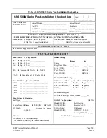
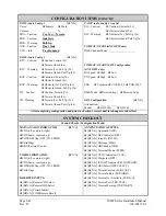
ILS Flight Check (GNS 530W)
1.
Tune an ILS at the local airport.
2.
Verify the audio ident and audio quality and verify that no objectionable electrical interference
such as magneto noise is present.
3.
Verify the Morse code decoder IDs the station (95% probability).
4.
Fly the approach.
5.
Verify NAV flag, GS flag, and CDI and VDI are operational.
6.
Verify BC annunciator.
5.6.5
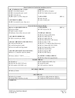
Autopilot Flight Check
1.
Enter and activate a flight plan on the 500W Series unit. For the GNS 530W ensure that GPS is
selected on the CDI. Engage the autopilot in the GPSS mode. Verify that the autopilot flies the
course.
2.
Disengage the autopilot and fly off course. Re-engage the autopilot (in GPSS mode) and verify
that it correctly intercepts the course and continues to fly it.
3.
Turn off the autopilot GPSS but leave the autopilot engaged in NAV mode. Verify that it
maintains the current course.
4.
(GNS 530W Only): Reselect the GPSS mode on the autopilot. Press the CDI key to select VLOC
on the GNS 530W. Verify that the GPSS mode disengages.
5.6.6
TAWS Audio Flight Check (for units with TAWS only)
NOTE
The TAWS volume needs to be loud enough to ensure that aural alerts are
audible under all anticipated noise environmental conditions. This check
verifies that TAWS aurals can be heard during flight, but the ambient noise
conditions under which it is verified are not worst-case. Consequently, the “Five
Hundred” callout should be louder than is required for the conditions under
which it is verified.
1.
Set up for an approach to the airport.
2.
During the approach, at approximately 500 ft AGL, the “Five Hundred” callout will occur.
Verify that “Five Hundred” can be easily heard and understood.
5.7 Database
Check
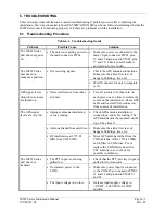
Check the aviation database to ensure it is current. The database information is displayed during the unit
display start-up sequence. To check the database:
2.
Turn off the 500W Series unit and then turn it on. The 500W Series unit will go through its
normal start-up sequence.
3.
Wait for the Aviation Database page to be displayed.
4.
Verify that the expiration date displayed has not passed.
If the database has expired, then remove and replace the aviation database card as described in the
following section, and see Section 1.7.1.
Содержание GNS 530W
Страница 2: ...500W Series Installation Manual 190 00357 02 Rev D...
Страница 12: ...Page viii 500W Series Installation Manual Rev D 190 00357 02 This Page Intentionally Left Blank...
Страница 33: ...500W Series Installation Manual Page 2 5 190 00357 02 Rev D Figure 2 1 GPS Antenna Installation Considerations...
Страница 40: ...Page 2 12 500W Series Installation Manual Rev D 190 00357 02 This Page Intentionally Left Blank...
Страница 122: ...Page 5 44 500W Series Installation Manual Rev D 190 00357 02 This Page Intentionally Left Blank...
Страница 130: ...Page 7 4 500W Series Installation Manual Rev D 190 00357 02 This Page Intentionally Left Blank...
Страница 132: ...Page 8 2 500W Series Installation Manual Rev D 190 00357 02 This Page Intentionally Left Blank...
Страница 134: ...Page A 2 500W Series Installation Manual Rev D 190 00357 02 This Page Intentionally Left Blank...
Страница 136: ...Page B 2 500W Series Installation Manual Rev D 190 00357 02 This Page Intentionally Left Blank...
Страница 137: ...500W Series Installation Manual Page C 1 190 00357 02 Rev D Appendix C RESERVED...
Страница 138: ...Page C 2 500W Series Installation Manual Rev D 190 00357 02 This Page Intentionally Left Blank...
Страница 148: ...Page E 6 500W Series Installation Manual Rev D 190 00357 02 This Page Intentionally Left Blank...
Страница 150: ...Page F 2 500W Series Installation Manual Rev D 190 00357 02 This Page Intentionally Left Blank...
Страница 160: ...Page G 6 500W Series Installation Manual Rev D 190 00357 02 This Page Intentionally Left Blank...
Страница 162: ...Page H 2 500W Series Installation Manual Rev D 190 00357 02 This Page Intentionally Left Blank...
Страница 163: ...500W Series Installation Manual Page H 3 190 00357 02 Rev D Figure H 1 500W Series Unit System Interface Diagram...
Страница 164: ...Page H 4 500W Series Installation Manual Rev D 190 00357 02 Figure H 2 GNS 530W Typical Installation Sheet 1 of 2...
Страница 165: ...500W Series Installation Manual Page H 5 190 00357 02 Rev D Figure H 2 GNS 530W Typical Installation Sheet 2 of 2...
Страница 166: ...Page H 6 500W Series Installation Manual Rev D 190 00357 02 Figure H 3 GPS 500W Typical Installation Sheet 1 of 2...
Страница 167: ...500W Series Installation Manual Page H 7 190 00357 02 Rev D Figure H 3 GPS 500W Typical Installation Sheet 2 of 2...
Страница 172: ...Page H 12 500W Series Installation Manual Rev D 190 00357 02 Figure H 6 Main Indicator Interconnect...
Страница 173: ...500W Series Installation Manual Page H 13 190 00357 02 Rev D Figure H 7 KI 209A Main Indicator Interconnect...
Страница 174: ...Page H 14 500W Series Installation Manual Rev D 190 00357 02 Figure H 8 KI 208A Main Indicator Interconnect...
Страница 175: ...500W Series Installation Manual Page H 15 190 00357 02 Rev D Figure H 9 RS 232 Serial Data Interconnect Sheet 1 of 2...
Страница 176: ...Page H 16 500W Series Installation Manual Rev D 190 00357 02 Figure H 9 RS 232 Serial Data Interconnect Sheet 2 of 2...
Страница 177: ...500W Series Installation Manual Page H 17 190 00357 02 Rev D Figure H 10 ARINC 429 EFIS Interconnect Sheet 1 of 2...
Страница 178: ...Page H 18 500W Series Installation Manual Rev D 190 00357 02 Figure H 10 ARINC 429 EFIS Interconnect Sheet 2 of 2...
Страница 188: ...Page H 28 500W Series Installation Manual Rev D 190 00357 02 Figure H 16 GTX 330 Interconnect...
Страница 189: ...500W Series Installation Manual Page H 29 190 00357 02 Rev D Figure H 17 Weather and Terrain Interconnect Sheet 1 of 2...
Страница 190: ...Page H 30 500W Series Installation Manual Rev D 190 00357 02 Figure H 17 Weather and Terrain Interconnect Sheet 2 of 2...
Страница 191: ...500W Series Installation Manual Page H 31 190 00357 02 Rev D Figure H 18 Audio Panel Interconnect Sheet 1 of 2...
Страница 192: ...Page H 32 500W Series Installation Manual Rev D 190 00357 02 Figure H 18 Audio Panel Interconnect Sheet 2 of 2...
Страница 193: ...500W Series Installation Manual Page H 33 190 00357 02 Rev D Figure H 19 VOR ILS Indicator Interconnect...
Страница 194: ...Page H 34 500W Series Installation Manual Rev D 190 00357 02 Figure H 20 RMI OBI Interconnect...
Страница 195: ...500W Series Installation Manual Page H 35 190 00357 02 Rev D Figure H 21 King Serial Panel DME Tuning Interconnect...
Страница 196: ...Page H 36 500W Series Installation Manual Rev D 190 00357 02 Figure H 22 King Serial Remote DME Tuning Interconnect...
Страница 197: ...500W Series Installation Manual Page H 37 190 00357 02 Rev D Figure H 23 Parallel 2 of 5 DME Tuning Interconnect...
Страница 198: ...Page H 38 500W Series Installation Manual Rev D 190 00357 02 Figure H 24 TAWS Interconnect...
Страница 199: ...500W Series Installation Manual Page H 39 190 00357 02 Rev D Figure H 25 Bendix King Analog Autopilot Interconnect...
Страница 200: ...Page H 40 500W Series Installation Manual Rev D 190 00357 02 Figure H 26 Century Autopilot Interconnect Sheet 1 of 2...
Страница 201: ...500W Series Installation Manual Page H 41 190 00357 02 Rev D H 26 Century Autopilot Interconnect Sheet 2 of 2...
Страница 202: ...Page H 42 500W Series Installation Manual Rev D 190 00357 02 Figure H 27 S TEC Autopilot Interconnect Sheet 1 of 2...
Страница 203: ...500W Series Installation Manual Page H 43 190 00357 02 Rev D Figure H 27 S TEC Autopilot Interconnect Sheet 2 of 2...
Страница 208: ...Page H 48 500W Series Installation Manual Rev D 190 00357 02 Figure H 30 Parallel Slip Code DME Tuning Interconnect...
Страница 209: ...500W Series Installation Manual Page H 49 190 00357 02 Rev D Figure H 31 Cessna Autopilot Interconnect...
Страница 210: ...Page H 50 500W Series Installation Manual Rev D 190 00357 02 Figure H 32 Bendix Autopilot Interconnect...
Страница 211: ...500W Series Installation Manual Page H 51 190 00357 02 Rev D Figure H 33 Switches Interconnect...
Страница 214: ...Page H 54 500W Series Installation Manual Rev D 190 00357 02 This Page Intentionally Left Blank...
Страница 215: ......
Страница 216: ......


