Page 5-40
500W Series Installation Manual
Rev. D
190-00357-02
5.7.1
Data Card Replacement
CAUTION
Handle the data cards carefully. Do not touch the connector edge of the data card.
To replace the data card do the following:
1.
Ensure that the 500W Series unit is turned off.
2.
Remove the data card by lifting the tab and pull card to extract from the unit.
3.
With the label facing up, insert the new data cards by pushing the card straight into the slot and
press until it is inserted fully. The aviation database card inserts into the left slot. The
TAWS/Terrain database card inserts into the right slot.
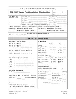
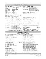
5.8 Airplane Flight Manual Supplement Checks
Ensure that the Airplane Flight Manual Supplement (AFMS) is completed and inserted in the Airplane
Flight Manual (AFM) or Pilot’s Operating Handbook (POH).
1.
Fill in the required airplane information in the AFMS.
2.
Fill in the appropriate checkbox in the Limitations section of the AFMS corresponding to the
type of GPS antenna that was installed.
3.
Fill in the appropriate checkbox in the Limitations section of the AFMS corresponding to the
autopilot coupling limitations.
NOTE
The GPS SELECT setting will determine if the transition into approach mode is
automatic or requires pilot acknowledgement of a message prompt. Refer to
GPS SELECT in Section 5.3.3
for additional details.
4.
Fill in the appropriate checkbox in the Normal Procedures section of the AFMS corresponding to
the autopilot mode transitions.
5.
Insert the completed AFMS into the AFM or POH.
Содержание GNS 530W
Страница 2: ...500W Series Installation Manual 190 00357 02 Rev D...
Страница 12: ...Page viii 500W Series Installation Manual Rev D 190 00357 02 This Page Intentionally Left Blank...
Страница 33: ...500W Series Installation Manual Page 2 5 190 00357 02 Rev D Figure 2 1 GPS Antenna Installation Considerations...
Страница 40: ...Page 2 12 500W Series Installation Manual Rev D 190 00357 02 This Page Intentionally Left Blank...
Страница 122: ...Page 5 44 500W Series Installation Manual Rev D 190 00357 02 This Page Intentionally Left Blank...
Страница 130: ...Page 7 4 500W Series Installation Manual Rev D 190 00357 02 This Page Intentionally Left Blank...
Страница 132: ...Page 8 2 500W Series Installation Manual Rev D 190 00357 02 This Page Intentionally Left Blank...
Страница 134: ...Page A 2 500W Series Installation Manual Rev D 190 00357 02 This Page Intentionally Left Blank...
Страница 136: ...Page B 2 500W Series Installation Manual Rev D 190 00357 02 This Page Intentionally Left Blank...
Страница 137: ...500W Series Installation Manual Page C 1 190 00357 02 Rev D Appendix C RESERVED...
Страница 138: ...Page C 2 500W Series Installation Manual Rev D 190 00357 02 This Page Intentionally Left Blank...
Страница 148: ...Page E 6 500W Series Installation Manual Rev D 190 00357 02 This Page Intentionally Left Blank...
Страница 150: ...Page F 2 500W Series Installation Manual Rev D 190 00357 02 This Page Intentionally Left Blank...
Страница 160: ...Page G 6 500W Series Installation Manual Rev D 190 00357 02 This Page Intentionally Left Blank...
Страница 162: ...Page H 2 500W Series Installation Manual Rev D 190 00357 02 This Page Intentionally Left Blank...
Страница 163: ...500W Series Installation Manual Page H 3 190 00357 02 Rev D Figure H 1 500W Series Unit System Interface Diagram...
Страница 164: ...Page H 4 500W Series Installation Manual Rev D 190 00357 02 Figure H 2 GNS 530W Typical Installation Sheet 1 of 2...
Страница 165: ...500W Series Installation Manual Page H 5 190 00357 02 Rev D Figure H 2 GNS 530W Typical Installation Sheet 2 of 2...
Страница 166: ...Page H 6 500W Series Installation Manual Rev D 190 00357 02 Figure H 3 GPS 500W Typical Installation Sheet 1 of 2...
Страница 167: ...500W Series Installation Manual Page H 7 190 00357 02 Rev D Figure H 3 GPS 500W Typical Installation Sheet 2 of 2...
Страница 172: ...Page H 12 500W Series Installation Manual Rev D 190 00357 02 Figure H 6 Main Indicator Interconnect...
Страница 173: ...500W Series Installation Manual Page H 13 190 00357 02 Rev D Figure H 7 KI 209A Main Indicator Interconnect...
Страница 174: ...Page H 14 500W Series Installation Manual Rev D 190 00357 02 Figure H 8 KI 208A Main Indicator Interconnect...
Страница 175: ...500W Series Installation Manual Page H 15 190 00357 02 Rev D Figure H 9 RS 232 Serial Data Interconnect Sheet 1 of 2...
Страница 176: ...Page H 16 500W Series Installation Manual Rev D 190 00357 02 Figure H 9 RS 232 Serial Data Interconnect Sheet 2 of 2...
Страница 177: ...500W Series Installation Manual Page H 17 190 00357 02 Rev D Figure H 10 ARINC 429 EFIS Interconnect Sheet 1 of 2...
Страница 178: ...Page H 18 500W Series Installation Manual Rev D 190 00357 02 Figure H 10 ARINC 429 EFIS Interconnect Sheet 2 of 2...
Страница 188: ...Page H 28 500W Series Installation Manual Rev D 190 00357 02 Figure H 16 GTX 330 Interconnect...
Страница 189: ...500W Series Installation Manual Page H 29 190 00357 02 Rev D Figure H 17 Weather and Terrain Interconnect Sheet 1 of 2...
Страница 190: ...Page H 30 500W Series Installation Manual Rev D 190 00357 02 Figure H 17 Weather and Terrain Interconnect Sheet 2 of 2...
Страница 191: ...500W Series Installation Manual Page H 31 190 00357 02 Rev D Figure H 18 Audio Panel Interconnect Sheet 1 of 2...
Страница 192: ...Page H 32 500W Series Installation Manual Rev D 190 00357 02 Figure H 18 Audio Panel Interconnect Sheet 2 of 2...
Страница 193: ...500W Series Installation Manual Page H 33 190 00357 02 Rev D Figure H 19 VOR ILS Indicator Interconnect...
Страница 194: ...Page H 34 500W Series Installation Manual Rev D 190 00357 02 Figure H 20 RMI OBI Interconnect...
Страница 195: ...500W Series Installation Manual Page H 35 190 00357 02 Rev D Figure H 21 King Serial Panel DME Tuning Interconnect...
Страница 196: ...Page H 36 500W Series Installation Manual Rev D 190 00357 02 Figure H 22 King Serial Remote DME Tuning Interconnect...
Страница 197: ...500W Series Installation Manual Page H 37 190 00357 02 Rev D Figure H 23 Parallel 2 of 5 DME Tuning Interconnect...
Страница 198: ...Page H 38 500W Series Installation Manual Rev D 190 00357 02 Figure H 24 TAWS Interconnect...
Страница 199: ...500W Series Installation Manual Page H 39 190 00357 02 Rev D Figure H 25 Bendix King Analog Autopilot Interconnect...
Страница 200: ...Page H 40 500W Series Installation Manual Rev D 190 00357 02 Figure H 26 Century Autopilot Interconnect Sheet 1 of 2...
Страница 201: ...500W Series Installation Manual Page H 41 190 00357 02 Rev D H 26 Century Autopilot Interconnect Sheet 2 of 2...
Страница 202: ...Page H 42 500W Series Installation Manual Rev D 190 00357 02 Figure H 27 S TEC Autopilot Interconnect Sheet 1 of 2...
Страница 203: ...500W Series Installation Manual Page H 43 190 00357 02 Rev D Figure H 27 S TEC Autopilot Interconnect Sheet 2 of 2...
Страница 208: ...Page H 48 500W Series Installation Manual Rev D 190 00357 02 Figure H 30 Parallel Slip Code DME Tuning Interconnect...
Страница 209: ...500W Series Installation Manual Page H 49 190 00357 02 Rev D Figure H 31 Cessna Autopilot Interconnect...
Страница 210: ...Page H 50 500W Series Installation Manual Rev D 190 00357 02 Figure H 32 Bendix Autopilot Interconnect...
Страница 211: ...500W Series Installation Manual Page H 51 190 00357 02 Rev D Figure H 33 Switches Interconnect...
Страница 214: ...Page H 54 500W Series Installation Manual Rev D 190 00357 02 This Page Intentionally Left Blank...
Страница 215: ......
Страница 216: ......


