500W Series Installation Manual
Page 1-13
190-00357-02
Rev. D
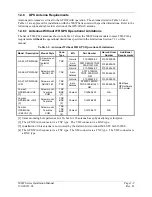
1.6.2 TSO
Deviations
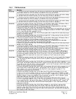
TSO Deviation
1. Garmin was granted a deviation from TSO-C34e to use RTCA/DO-178B instead of RTCA/DO-178A to
demonstrate compliance for the verification and validation of the computer software.
TSO-C34e
2. Garmin was granted a deviation from TSO-C34e to use RTCA/DO-160C instead of RTCA/DO-160B as
the standard for Environmental Conditions and Test Procedures of Airborne Equipment.
1. Garmin was granted a deviation from TSO-C36e to use RTCA/DO-178B instead of RTCA/DO-178A to
demonstrate compliance for the verification and validation of the computer software.
TSO-C36e
2. Garmin was granted a deviation from TSO-C36e to use RTCA/DO-160C instead of RTCA/DO-160B as
the standard for Environmental Conditions and Test Procedures of Airborne Equipment.
TSO-C37d
1. Garmin was granted a deviation from TSO-C37d to use RTCA/DO-178B instead of RTCA/DO-178A to
demonstrate compliance for the verification and validation of the computer software.
2. Garmin was granted a deviation from TSO-C37d paragraph (a)(1) to allow using RTCA /DO-186A
instead of RTCA/DO-186 to specify minimum performance standards.
3. Garmin was granted a deviation from TSO-C37d to allow a 6dB reduction of transmitter power during the
Normal Operating Conditions – Emergency Operation Voltage as described in RTCA/DO-186A paragraph
2.5.13.1 and RTCA/DO-160C paragraph 16.5.2.1.
4. Garmin was granted a deviation from TSO-C37d paragraph (a)(5) to allow 8.33 kHz channel spacing in
addition to the 25 kHz spacing.
5. Garmin was granted a deviation from TSO-C37d paragraph (b)(1) to allow marking to call our 8.33 kHz
channel spacing in addition to the 25 kHz spacing.
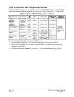
TSO-C38d
1. Garmin was granted a deviation from TSO-C38d to use RTCA/DO-178B instead of RTCA/DO-178A to
demonstrate compliance for the verification and validation of the computer software.
2. Garmin was granted a deviation from TSO-C38d paragraph (a)(1) to allow using RTCA /DO-186A
instead of RTCA/DO-186 to specify minimum performance standards.
3. Garmin was granted a deviation from TSO-C38d paragraph (a)(5) to allow 8.33 kHz channel spacing in
addition to the 25 kHz spacing.
TSO-C40c
1. Garmin was granted a deviation from TSO-C40c to use RTCA/DO-178B instead of RTCA/DO-178A to
demonstrate compliance for the verification and validation of the computer software.
2. Garmin was granted a deviation from TSO-C40c to use RTCA/DO-160C instead of RTCA/DO-160B as
the standard for Environmental Conditions and Test Procedures for Airborne Equipment.
TSO-C113
1. Garmin was granted a deviation from TSO-C113 section 2.1.2 (4) to use RTCA/DO-178B instead of
RTCA/DO-178A to demonstrate compliance for the verification and validation of the computer software.
2. Garmin was granted a deviation from TSO-C113 section 2.1.2 (3) to use RTCA/DO-160D instead of
RTCA/DO-160B as the standard for Environmental Conditions and Test Procedures for Airborne
Equipment.
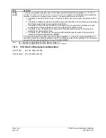
TSO-C146a
1. Garmin was granted a deviation from TSO-C146a for the requirement to use as a specific “NAV” labeled
key. RTCA/DO-229c Table 2-5 lists the function “Access to primary navigation display (Section 2.2.1.4.1)”
with a label “NAV”.
2. Garmin was granted a deviation from TSO-C146a not to implement RTCA/DO-229C paragraph 2.2.3.2.2
which states “The equipment shall allow the pilot to initiate the missed approach with manual action. It shall
be possible to take this action before crossing the MAWP, in which case the equipment shall automatically
initiate the missed approach procedure at the MAWP.”
3. Garmin was granted a deviation from TSO-C146a not to implement RTCA/DO-229C paragraph 2.2.4.2.3
which states “If the aircraft is past the FPAP – (length offset), and the pilot has not already activated the
missed approach, the receiver shall automatically transition to missed approach guidance.” This
requirement is being eliminated in DO-229D.
4. Garmin was granted a deviation from TSO-C146a from RTCA/DO-229C paragraphs 2.2.4.6.4 and
2.2.5.6.4 not to use the low altitude alerting function when the 500W series unit has TERRAIN or TAWS
enabled and is not in one of the following states: FAIL, N/A, TEST, or INHIBIT. When neither TERRAIN nor
TAWS is enabled, or when one is enabled but the current state is FAIL, N/A, TEST, or INHIBIT, the low
altitude alert described in DO-229C 2.2.4.6.4 and 2.2.5.6.4 is used.
5. Garmin was granted a deviation from TSO-C146a not to implement RTCA/DO-229C paragraph
2.2.1.4.9.c which states “BRG to or from a VOR: The bearing is based on the true-to-magnetic conversion
at the waypoint location, using the same magnetic conversion as used to define the path.” Instead, the
“user” (current) location will be used. The RTCA/DO-229C paragraph 2.2.1.4.9.c requirement is being
eliminated in DO-229D.
6. Garmin was granted a deviation from TSO-C146a paragraph 4.b. which defines “each separate
component that is easily removable (without hand tools), each interchangeable element, and each
separate subassembly of the article that the manufacturer determines may be interchangeable must be
permanently and legibly marked with at least the name of the manufacturer, manufacturer’s subassembly
part number, and the TSO number.”
Содержание GNS 530W
Страница 2: ...500W Series Installation Manual 190 00357 02 Rev D...
Страница 12: ...Page viii 500W Series Installation Manual Rev D 190 00357 02 This Page Intentionally Left Blank...
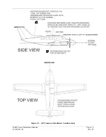
Страница 33: ...500W Series Installation Manual Page 2 5 190 00357 02 Rev D Figure 2 1 GPS Antenna Installation Considerations...
Страница 40: ...Page 2 12 500W Series Installation Manual Rev D 190 00357 02 This Page Intentionally Left Blank...
Страница 122: ...Page 5 44 500W Series Installation Manual Rev D 190 00357 02 This Page Intentionally Left Blank...
Страница 130: ...Page 7 4 500W Series Installation Manual Rev D 190 00357 02 This Page Intentionally Left Blank...
Страница 132: ...Page 8 2 500W Series Installation Manual Rev D 190 00357 02 This Page Intentionally Left Blank...
Страница 134: ...Page A 2 500W Series Installation Manual Rev D 190 00357 02 This Page Intentionally Left Blank...
Страница 136: ...Page B 2 500W Series Installation Manual Rev D 190 00357 02 This Page Intentionally Left Blank...
Страница 137: ...500W Series Installation Manual Page C 1 190 00357 02 Rev D Appendix C RESERVED...
Страница 138: ...Page C 2 500W Series Installation Manual Rev D 190 00357 02 This Page Intentionally Left Blank...
Страница 148: ...Page E 6 500W Series Installation Manual Rev D 190 00357 02 This Page Intentionally Left Blank...
Страница 150: ...Page F 2 500W Series Installation Manual Rev D 190 00357 02 This Page Intentionally Left Blank...
Страница 160: ...Page G 6 500W Series Installation Manual Rev D 190 00357 02 This Page Intentionally Left Blank...
Страница 162: ...Page H 2 500W Series Installation Manual Rev D 190 00357 02 This Page Intentionally Left Blank...
Страница 163: ...500W Series Installation Manual Page H 3 190 00357 02 Rev D Figure H 1 500W Series Unit System Interface Diagram...
Страница 164: ...Page H 4 500W Series Installation Manual Rev D 190 00357 02 Figure H 2 GNS 530W Typical Installation Sheet 1 of 2...
Страница 165: ...500W Series Installation Manual Page H 5 190 00357 02 Rev D Figure H 2 GNS 530W Typical Installation Sheet 2 of 2...
Страница 166: ...Page H 6 500W Series Installation Manual Rev D 190 00357 02 Figure H 3 GPS 500W Typical Installation Sheet 1 of 2...
Страница 167: ...500W Series Installation Manual Page H 7 190 00357 02 Rev D Figure H 3 GPS 500W Typical Installation Sheet 2 of 2...
Страница 172: ...Page H 12 500W Series Installation Manual Rev D 190 00357 02 Figure H 6 Main Indicator Interconnect...
Страница 173: ...500W Series Installation Manual Page H 13 190 00357 02 Rev D Figure H 7 KI 209A Main Indicator Interconnect...
Страница 174: ...Page H 14 500W Series Installation Manual Rev D 190 00357 02 Figure H 8 KI 208A Main Indicator Interconnect...
Страница 175: ...500W Series Installation Manual Page H 15 190 00357 02 Rev D Figure H 9 RS 232 Serial Data Interconnect Sheet 1 of 2...
Страница 176: ...Page H 16 500W Series Installation Manual Rev D 190 00357 02 Figure H 9 RS 232 Serial Data Interconnect Sheet 2 of 2...
Страница 177: ...500W Series Installation Manual Page H 17 190 00357 02 Rev D Figure H 10 ARINC 429 EFIS Interconnect Sheet 1 of 2...
Страница 178: ...Page H 18 500W Series Installation Manual Rev D 190 00357 02 Figure H 10 ARINC 429 EFIS Interconnect Sheet 2 of 2...
Страница 188: ...Page H 28 500W Series Installation Manual Rev D 190 00357 02 Figure H 16 GTX 330 Interconnect...
Страница 189: ...500W Series Installation Manual Page H 29 190 00357 02 Rev D Figure H 17 Weather and Terrain Interconnect Sheet 1 of 2...
Страница 190: ...Page H 30 500W Series Installation Manual Rev D 190 00357 02 Figure H 17 Weather and Terrain Interconnect Sheet 2 of 2...
Страница 191: ...500W Series Installation Manual Page H 31 190 00357 02 Rev D Figure H 18 Audio Panel Interconnect Sheet 1 of 2...
Страница 192: ...Page H 32 500W Series Installation Manual Rev D 190 00357 02 Figure H 18 Audio Panel Interconnect Sheet 2 of 2...
Страница 193: ...500W Series Installation Manual Page H 33 190 00357 02 Rev D Figure H 19 VOR ILS Indicator Interconnect...
Страница 194: ...Page H 34 500W Series Installation Manual Rev D 190 00357 02 Figure H 20 RMI OBI Interconnect...
Страница 195: ...500W Series Installation Manual Page H 35 190 00357 02 Rev D Figure H 21 King Serial Panel DME Tuning Interconnect...
Страница 196: ...Page H 36 500W Series Installation Manual Rev D 190 00357 02 Figure H 22 King Serial Remote DME Tuning Interconnect...
Страница 197: ...500W Series Installation Manual Page H 37 190 00357 02 Rev D Figure H 23 Parallel 2 of 5 DME Tuning Interconnect...
Страница 198: ...Page H 38 500W Series Installation Manual Rev D 190 00357 02 Figure H 24 TAWS Interconnect...
Страница 199: ...500W Series Installation Manual Page H 39 190 00357 02 Rev D Figure H 25 Bendix King Analog Autopilot Interconnect...
Страница 200: ...Page H 40 500W Series Installation Manual Rev D 190 00357 02 Figure H 26 Century Autopilot Interconnect Sheet 1 of 2...
Страница 201: ...500W Series Installation Manual Page H 41 190 00357 02 Rev D H 26 Century Autopilot Interconnect Sheet 2 of 2...
Страница 202: ...Page H 42 500W Series Installation Manual Rev D 190 00357 02 Figure H 27 S TEC Autopilot Interconnect Sheet 1 of 2...
Страница 203: ...500W Series Installation Manual Page H 43 190 00357 02 Rev D Figure H 27 S TEC Autopilot Interconnect Sheet 2 of 2...
Страница 208: ...Page H 48 500W Series Installation Manual Rev D 190 00357 02 Figure H 30 Parallel Slip Code DME Tuning Interconnect...
Страница 209: ...500W Series Installation Manual Page H 49 190 00357 02 Rev D Figure H 31 Cessna Autopilot Interconnect...
Страница 210: ...Page H 50 500W Series Installation Manual Rev D 190 00357 02 Figure H 32 Bendix Autopilot Interconnect...
Страница 211: ...500W Series Installation Manual Page H 51 190 00357 02 Rev D Figure H 33 Switches Interconnect...
Страница 214: ...Page H 54 500W Series Installation Manual Rev D 190 00357 02 This Page Intentionally Left Blank...
Страница 215: ......
Страница 216: ......


