Page 1-10
500W Series Installation Manual
Rev. D
190-00357-02
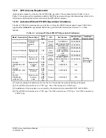
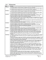
1.4.8.2 Antennas With IFR GPS Operational Limitations
The list of TSO-C144 antennas shown in Table 1-3 allow the 500W Series models to meet TSO-C146a
requirements with the operational limitations specified in the Limitations Section 7.1.1 of this manual.
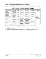
Table 1-3. Antennas With IFR GPS Operational Limitations
Model / Description
Mount Style
Conn
Type
Mfr Part
Number
Garmin Order
Number
Additional
Requirements
GA 56A,
GPS/WAAS
Antenna [3]
Screw Mount,
ARINC 743
Footprint
BNC Garmin
011-01154-00 010-10599-00
GA 56W,
GPS/WAAS
Antenna [3]
Stud Mount ,
Teardrop
Footprint [1]
BNC Garmin
011-01111-00 010-10561-01
GA 57, GPS/WAAS
and FIS Antenna
[3]
Screw Mount,
ARINC 743
Footprint
BNC
TNC
[4]
Garmin 011-01032-00
010-10604-00
Garmin AT
590-1104
N/A
A33, GPS/WAAS
Antenna
Screw Mount
TNC
Aero
Antenna
AT575-9UW-TNCF-
000-05-26-NM
N/A
Garmin AT
590-1112
013-00113-00
A34, GPS/WAAS
Antenna
Screw Mount,
Teardrop
Footprint [2]
TNC
Aero
Antenna
AT575-93W-TNCF-
000-05-26-NM
013-00113-00
Operational
limitations in
Section 7.1.1
of this manual
apply.
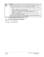
[1] Same footprint and mounting hole pattern as GA 56.
[2] Same mounting hole pattern as GA 56, but A34 antenna has a physically larger footprint
.
[3] Antenna is not compatible with SATCOM. An alternate antenna should be used for installations
equipped with SATCOM.
[4] The GPS/WAAS antenna connector is a BNC type. The XM antenna connector is a TNC type.
Содержание GNS 530W
Страница 2: ...500W Series Installation Manual 190 00357 02 Rev D...
Страница 12: ...Page viii 500W Series Installation Manual Rev D 190 00357 02 This Page Intentionally Left Blank...
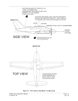
Страница 33: ...500W Series Installation Manual Page 2 5 190 00357 02 Rev D Figure 2 1 GPS Antenna Installation Considerations...
Страница 40: ...Page 2 12 500W Series Installation Manual Rev D 190 00357 02 This Page Intentionally Left Blank...
Страница 122: ...Page 5 44 500W Series Installation Manual Rev D 190 00357 02 This Page Intentionally Left Blank...
Страница 130: ...Page 7 4 500W Series Installation Manual Rev D 190 00357 02 This Page Intentionally Left Blank...
Страница 132: ...Page 8 2 500W Series Installation Manual Rev D 190 00357 02 This Page Intentionally Left Blank...
Страница 134: ...Page A 2 500W Series Installation Manual Rev D 190 00357 02 This Page Intentionally Left Blank...
Страница 136: ...Page B 2 500W Series Installation Manual Rev D 190 00357 02 This Page Intentionally Left Blank...
Страница 137: ...500W Series Installation Manual Page C 1 190 00357 02 Rev D Appendix C RESERVED...
Страница 138: ...Page C 2 500W Series Installation Manual Rev D 190 00357 02 This Page Intentionally Left Blank...
Страница 148: ...Page E 6 500W Series Installation Manual Rev D 190 00357 02 This Page Intentionally Left Blank...
Страница 150: ...Page F 2 500W Series Installation Manual Rev D 190 00357 02 This Page Intentionally Left Blank...
Страница 160: ...Page G 6 500W Series Installation Manual Rev D 190 00357 02 This Page Intentionally Left Blank...
Страница 162: ...Page H 2 500W Series Installation Manual Rev D 190 00357 02 This Page Intentionally Left Blank...
Страница 163: ...500W Series Installation Manual Page H 3 190 00357 02 Rev D Figure H 1 500W Series Unit System Interface Diagram...
Страница 164: ...Page H 4 500W Series Installation Manual Rev D 190 00357 02 Figure H 2 GNS 530W Typical Installation Sheet 1 of 2...
Страница 165: ...500W Series Installation Manual Page H 5 190 00357 02 Rev D Figure H 2 GNS 530W Typical Installation Sheet 2 of 2...
Страница 166: ...Page H 6 500W Series Installation Manual Rev D 190 00357 02 Figure H 3 GPS 500W Typical Installation Sheet 1 of 2...
Страница 167: ...500W Series Installation Manual Page H 7 190 00357 02 Rev D Figure H 3 GPS 500W Typical Installation Sheet 2 of 2...
Страница 172: ...Page H 12 500W Series Installation Manual Rev D 190 00357 02 Figure H 6 Main Indicator Interconnect...
Страница 173: ...500W Series Installation Manual Page H 13 190 00357 02 Rev D Figure H 7 KI 209A Main Indicator Interconnect...
Страница 174: ...Page H 14 500W Series Installation Manual Rev D 190 00357 02 Figure H 8 KI 208A Main Indicator Interconnect...
Страница 175: ...500W Series Installation Manual Page H 15 190 00357 02 Rev D Figure H 9 RS 232 Serial Data Interconnect Sheet 1 of 2...
Страница 176: ...Page H 16 500W Series Installation Manual Rev D 190 00357 02 Figure H 9 RS 232 Serial Data Interconnect Sheet 2 of 2...
Страница 177: ...500W Series Installation Manual Page H 17 190 00357 02 Rev D Figure H 10 ARINC 429 EFIS Interconnect Sheet 1 of 2...
Страница 178: ...Page H 18 500W Series Installation Manual Rev D 190 00357 02 Figure H 10 ARINC 429 EFIS Interconnect Sheet 2 of 2...
Страница 188: ...Page H 28 500W Series Installation Manual Rev D 190 00357 02 Figure H 16 GTX 330 Interconnect...
Страница 189: ...500W Series Installation Manual Page H 29 190 00357 02 Rev D Figure H 17 Weather and Terrain Interconnect Sheet 1 of 2...
Страница 190: ...Page H 30 500W Series Installation Manual Rev D 190 00357 02 Figure H 17 Weather and Terrain Interconnect Sheet 2 of 2...
Страница 191: ...500W Series Installation Manual Page H 31 190 00357 02 Rev D Figure H 18 Audio Panel Interconnect Sheet 1 of 2...
Страница 192: ...Page H 32 500W Series Installation Manual Rev D 190 00357 02 Figure H 18 Audio Panel Interconnect Sheet 2 of 2...
Страница 193: ...500W Series Installation Manual Page H 33 190 00357 02 Rev D Figure H 19 VOR ILS Indicator Interconnect...
Страница 194: ...Page H 34 500W Series Installation Manual Rev D 190 00357 02 Figure H 20 RMI OBI Interconnect...
Страница 195: ...500W Series Installation Manual Page H 35 190 00357 02 Rev D Figure H 21 King Serial Panel DME Tuning Interconnect...
Страница 196: ...Page H 36 500W Series Installation Manual Rev D 190 00357 02 Figure H 22 King Serial Remote DME Tuning Interconnect...
Страница 197: ...500W Series Installation Manual Page H 37 190 00357 02 Rev D Figure H 23 Parallel 2 of 5 DME Tuning Interconnect...
Страница 198: ...Page H 38 500W Series Installation Manual Rev D 190 00357 02 Figure H 24 TAWS Interconnect...
Страница 199: ...500W Series Installation Manual Page H 39 190 00357 02 Rev D Figure H 25 Bendix King Analog Autopilot Interconnect...
Страница 200: ...Page H 40 500W Series Installation Manual Rev D 190 00357 02 Figure H 26 Century Autopilot Interconnect Sheet 1 of 2...
Страница 201: ...500W Series Installation Manual Page H 41 190 00357 02 Rev D H 26 Century Autopilot Interconnect Sheet 2 of 2...
Страница 202: ...Page H 42 500W Series Installation Manual Rev D 190 00357 02 Figure H 27 S TEC Autopilot Interconnect Sheet 1 of 2...
Страница 203: ...500W Series Installation Manual Page H 43 190 00357 02 Rev D Figure H 27 S TEC Autopilot Interconnect Sheet 2 of 2...
Страница 208: ...Page H 48 500W Series Installation Manual Rev D 190 00357 02 Figure H 30 Parallel Slip Code DME Tuning Interconnect...
Страница 209: ...500W Series Installation Manual Page H 49 190 00357 02 Rev D Figure H 31 Cessna Autopilot Interconnect...
Страница 210: ...Page H 50 500W Series Installation Manual Rev D 190 00357 02 Figure H 32 Bendix Autopilot Interconnect...
Страница 211: ...500W Series Installation Manual Page H 51 190 00357 02 Rev D Figure H 33 Switches Interconnect...
Страница 214: ...Page H 54 500W Series Installation Manual Rev D 190 00357 02 This Page Intentionally Left Blank...
Страница 215: ......
Страница 216: ......


