Page 1-14
500W Series Installation Manual
Rev. D
190-00357-02
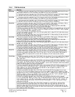
TSO Deviation
7.
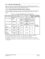
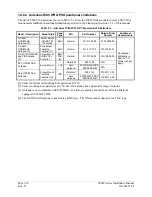
Garmin was granted a deviation from TSO-C146a from RTCA/DO-229C paragraphs 2.1.1.10, 2.1.1.7,
2.1.1.8.1, 2.1.1.8.2, 2.1.1.9, 2.1.2.1, 2.1.3.1, 2.1.4.1.4, 2.1.4.1.5 and 2.1.5.1 in the form of an operational
limitation to achieve an equivalent level of safety. The operational limitation is based on:
a. The ability to use antennas that may not meet the minimum gain performance requirements of DO-
228.
b. The ability to mitigate the effects of the different gain characteristics of those antennas by increasing
the effective mask angle through operational limitations.
c. The ability to further increase the effective mask angle, through operational limitations, to a level
commensurate with test conditions used in the original TSO qualification tests.
d. The ability to use -128 dBmic as the minimum GPS satellite signal-in-space for the purpose of
assessing the operational limitation.
e. The ability to use -128 dBmic as the minimum SBAS satellite signal-in-space for the purpose of
assessing the operational limitation. NOTE 1
C146a
cont’d
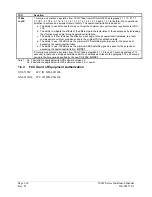
8. Garmin was granted a deviation from TSO-C146a paragraph 2.1.1.9 to use 20 seconds (instead of 10
seconds) to reacquire a dropped satellite under the conditions described in the paragraph. The 20 second
period is the time period specified by the new DO-229d. NOTE 1
Note 1: No. 7 deviation is applicable with GPS software version 2.X
No. 8 deviation is applicable with GPS software version 3.0 or newer.
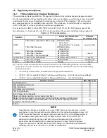
1.6.3
FCC Grant of Equipment Authorization
GNS 530W
FCC ID: IPH-0021400
GNS 530AW FCC ID: IPH-0061100
Содержание GNS 530W
Страница 2: ...500W Series Installation Manual 190 00357 02 Rev D...
Страница 12: ...Page viii 500W Series Installation Manual Rev D 190 00357 02 This Page Intentionally Left Blank...
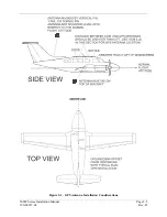
Страница 33: ...500W Series Installation Manual Page 2 5 190 00357 02 Rev D Figure 2 1 GPS Antenna Installation Considerations...
Страница 40: ...Page 2 12 500W Series Installation Manual Rev D 190 00357 02 This Page Intentionally Left Blank...
Страница 122: ...Page 5 44 500W Series Installation Manual Rev D 190 00357 02 This Page Intentionally Left Blank...
Страница 130: ...Page 7 4 500W Series Installation Manual Rev D 190 00357 02 This Page Intentionally Left Blank...
Страница 132: ...Page 8 2 500W Series Installation Manual Rev D 190 00357 02 This Page Intentionally Left Blank...
Страница 134: ...Page A 2 500W Series Installation Manual Rev D 190 00357 02 This Page Intentionally Left Blank...
Страница 136: ...Page B 2 500W Series Installation Manual Rev D 190 00357 02 This Page Intentionally Left Blank...
Страница 137: ...500W Series Installation Manual Page C 1 190 00357 02 Rev D Appendix C RESERVED...
Страница 138: ...Page C 2 500W Series Installation Manual Rev D 190 00357 02 This Page Intentionally Left Blank...
Страница 148: ...Page E 6 500W Series Installation Manual Rev D 190 00357 02 This Page Intentionally Left Blank...
Страница 150: ...Page F 2 500W Series Installation Manual Rev D 190 00357 02 This Page Intentionally Left Blank...
Страница 160: ...Page G 6 500W Series Installation Manual Rev D 190 00357 02 This Page Intentionally Left Blank...
Страница 162: ...Page H 2 500W Series Installation Manual Rev D 190 00357 02 This Page Intentionally Left Blank...
Страница 163: ...500W Series Installation Manual Page H 3 190 00357 02 Rev D Figure H 1 500W Series Unit System Interface Diagram...
Страница 164: ...Page H 4 500W Series Installation Manual Rev D 190 00357 02 Figure H 2 GNS 530W Typical Installation Sheet 1 of 2...
Страница 165: ...500W Series Installation Manual Page H 5 190 00357 02 Rev D Figure H 2 GNS 530W Typical Installation Sheet 2 of 2...
Страница 166: ...Page H 6 500W Series Installation Manual Rev D 190 00357 02 Figure H 3 GPS 500W Typical Installation Sheet 1 of 2...
Страница 167: ...500W Series Installation Manual Page H 7 190 00357 02 Rev D Figure H 3 GPS 500W Typical Installation Sheet 2 of 2...
Страница 172: ...Page H 12 500W Series Installation Manual Rev D 190 00357 02 Figure H 6 Main Indicator Interconnect...
Страница 173: ...500W Series Installation Manual Page H 13 190 00357 02 Rev D Figure H 7 KI 209A Main Indicator Interconnect...
Страница 174: ...Page H 14 500W Series Installation Manual Rev D 190 00357 02 Figure H 8 KI 208A Main Indicator Interconnect...
Страница 175: ...500W Series Installation Manual Page H 15 190 00357 02 Rev D Figure H 9 RS 232 Serial Data Interconnect Sheet 1 of 2...
Страница 176: ...Page H 16 500W Series Installation Manual Rev D 190 00357 02 Figure H 9 RS 232 Serial Data Interconnect Sheet 2 of 2...
Страница 177: ...500W Series Installation Manual Page H 17 190 00357 02 Rev D Figure H 10 ARINC 429 EFIS Interconnect Sheet 1 of 2...
Страница 178: ...Page H 18 500W Series Installation Manual Rev D 190 00357 02 Figure H 10 ARINC 429 EFIS Interconnect Sheet 2 of 2...
Страница 188: ...Page H 28 500W Series Installation Manual Rev D 190 00357 02 Figure H 16 GTX 330 Interconnect...
Страница 189: ...500W Series Installation Manual Page H 29 190 00357 02 Rev D Figure H 17 Weather and Terrain Interconnect Sheet 1 of 2...
Страница 190: ...Page H 30 500W Series Installation Manual Rev D 190 00357 02 Figure H 17 Weather and Terrain Interconnect Sheet 2 of 2...
Страница 191: ...500W Series Installation Manual Page H 31 190 00357 02 Rev D Figure H 18 Audio Panel Interconnect Sheet 1 of 2...
Страница 192: ...Page H 32 500W Series Installation Manual Rev D 190 00357 02 Figure H 18 Audio Panel Interconnect Sheet 2 of 2...
Страница 193: ...500W Series Installation Manual Page H 33 190 00357 02 Rev D Figure H 19 VOR ILS Indicator Interconnect...
Страница 194: ...Page H 34 500W Series Installation Manual Rev D 190 00357 02 Figure H 20 RMI OBI Interconnect...
Страница 195: ...500W Series Installation Manual Page H 35 190 00357 02 Rev D Figure H 21 King Serial Panel DME Tuning Interconnect...
Страница 196: ...Page H 36 500W Series Installation Manual Rev D 190 00357 02 Figure H 22 King Serial Remote DME Tuning Interconnect...
Страница 197: ...500W Series Installation Manual Page H 37 190 00357 02 Rev D Figure H 23 Parallel 2 of 5 DME Tuning Interconnect...
Страница 198: ...Page H 38 500W Series Installation Manual Rev D 190 00357 02 Figure H 24 TAWS Interconnect...
Страница 199: ...500W Series Installation Manual Page H 39 190 00357 02 Rev D Figure H 25 Bendix King Analog Autopilot Interconnect...
Страница 200: ...Page H 40 500W Series Installation Manual Rev D 190 00357 02 Figure H 26 Century Autopilot Interconnect Sheet 1 of 2...
Страница 201: ...500W Series Installation Manual Page H 41 190 00357 02 Rev D H 26 Century Autopilot Interconnect Sheet 2 of 2...
Страница 202: ...Page H 42 500W Series Installation Manual Rev D 190 00357 02 Figure H 27 S TEC Autopilot Interconnect Sheet 1 of 2...
Страница 203: ...500W Series Installation Manual Page H 43 190 00357 02 Rev D Figure H 27 S TEC Autopilot Interconnect Sheet 2 of 2...
Страница 208: ...Page H 48 500W Series Installation Manual Rev D 190 00357 02 Figure H 30 Parallel Slip Code DME Tuning Interconnect...
Страница 209: ...500W Series Installation Manual Page H 49 190 00357 02 Rev D Figure H 31 Cessna Autopilot Interconnect...
Страница 210: ...Page H 50 500W Series Installation Manual Rev D 190 00357 02 Figure H 32 Bendix Autopilot Interconnect...
Страница 211: ...500W Series Installation Manual Page H 51 190 00357 02 Rev D Figure H 33 Switches Interconnect...
Страница 214: ...Page H 54 500W Series Installation Manual Rev D 190 00357 02 This Page Intentionally Left Blank...
Страница 215: ......
Страница 216: ......


