13–8–612 Page 27
Changing the oil will be of little benefit if done in a care-
less manner.
COMPRESSOR OIL FILTER (FIGURE 1–2, Section
1, page 2) – This replaceable element filter is a vital part
in maintaining a trouble–free compressor, since it re-
moves dirt and abrasives from the circulated oil. The
filter is equipped with a relief valve that opens in the
event the element becomes dirty enough to block the
flow of oil. Use only the replacement element shown
on the filter tag or refer to the parts list for the part num-
ber.
Use the following procedure to replace the filter ele-
ment. Do not disturb the piping.
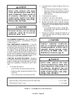
Improper oil filter maintenance will
cause damage to equipment. Replace
filter element every 1000 hours of op-
eration. More frequent replacement
could be required depending on oper-
ating conditions. A filter element left
in service too long may damage
equipment.
1.
Stop unit and be sure no air pressure is in the oil
reservoir.
2.
Remove the spin–on element.
3.
Clean the gasket face of the filter body.
4.
Coat the new element gasket with clean lubricant
used in the unit.
5.
Screw new element on filter body and tighten by
hand. DO NOT OVERTIGHTEN ELEMENT.
6.
Run the unit and check for leaks.
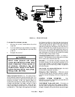
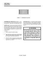
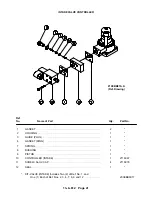
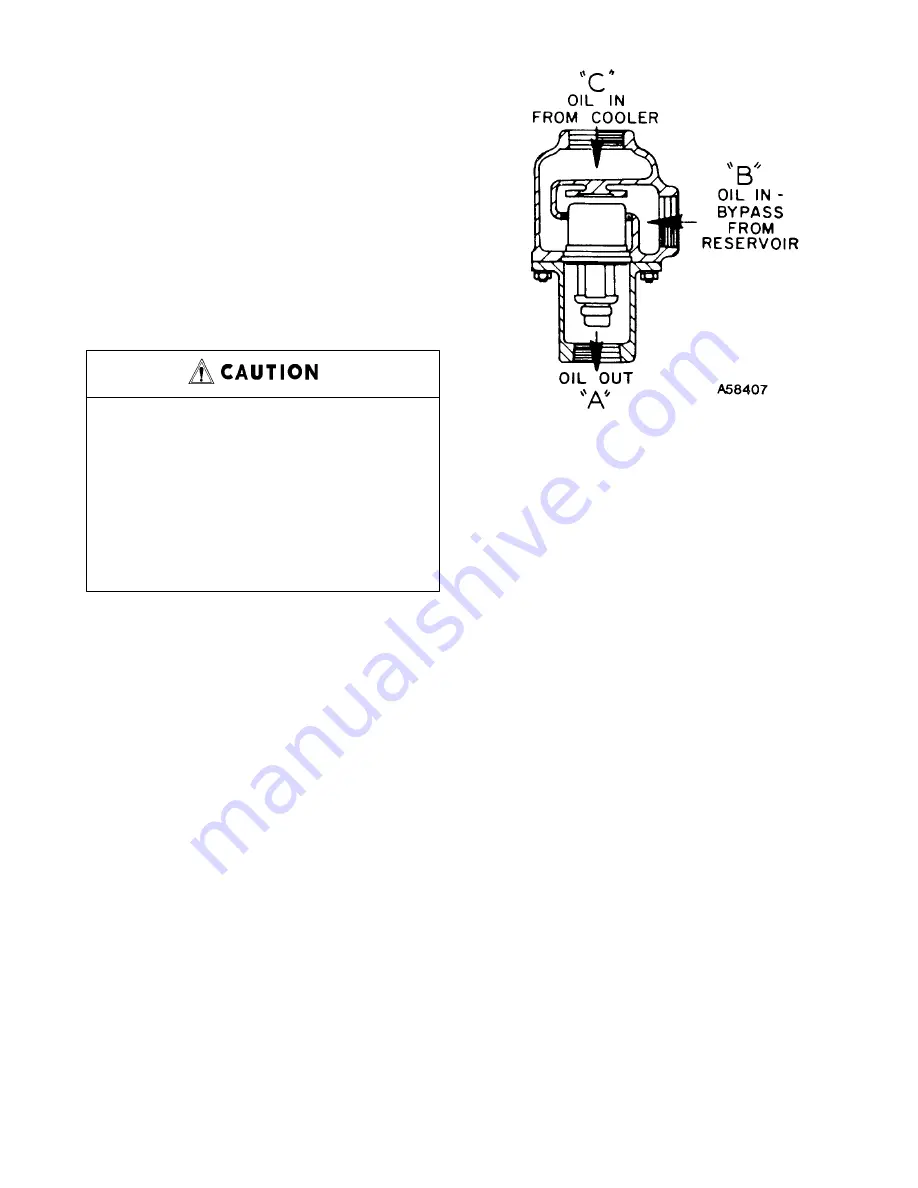
THERMAL CONTROL (THERMOSTATIC MIXING)
VALVE (FIGURE 5–4) is installed in system as shown
in FIGURE 4–1, Section 4, page 15. This valve is used
to control temperature of the oil both air–cooled radia-
tor and water–cooled heat exchanger type oil cooler
systems. On start–up with unit cold, element is open to
bypass, allowing oil to pass directly from the reservoir
to compressor during warm–up. As oil warms, element
gradually closes to the bypass allowing more of the oil
from the cooler to mix with oil from the bypass.
After the unit is warmed up, the mixing valve maintains
oil injection temperature into the compressor at a mini-
mum of 170
_
F. This system provides proper com-
FIGURE 5–4 – THERMOSTATIC MIXING VALVE
pressor warm–up and prevents moisture contamina-
tion of the oil.
To check the element, heat in oil – it should be fully ex-
tended at 170
_
F. If the unit shuts down due to high air
discharge temperature, the cause may be that the ele-
ment is stuck open to the bypass, in which case bypass
lines (FIGURE 4–1, Section 4, page 15) will be hot to
touch and lines out of mixing valve much cooler. When
flushing the oil system, remove the mixing valve and
clean all parts thoroughly.
OIL RESERVOIR – The oil reservoir–separator, lo-
cated in the compressor housing, combines multiple
functions into one vessel. The lower half is the oil reser-
voir, providing oil storage capacity for the system and
the top portion, a primary oil separation means. The
reservoir also provides limited air storage for control
and gauge actuation.
COMPRESSOR OIL SEPARATOR – The compressor
oil separator located on top of the filter housing,
screwed onto a fitting, features a renewable spin–on
type separator element and provides the final removal
of oil from the air flow.
Oil carry–over through the service lines may be caused
by a faulty oil separator, overfilling of the oil reservoir,
oil that foams, oil return line malfunction, or water con-
densate in the oil. If oil carryover occurs, inspect the
separator only after it is determined that the oil level is
not too high, the oil is not foaming excessively, the oil
return tube from the bottom of the separator to the com-
Содержание EBB BB-7.5 HP
Страница 12: ...13 8 612 Page 2 FIGURE 1 2 PACKAGE COMPRESSOR MOTOR SIDE FIGURE 1 3 PACKAGE BELT GUARD SIDE...
Страница 13: ...13 8 612 Page 3 FIGURE 1 4 PACKAGE CONTROLLER END...
Страница 16: ...13 8 612 Page 6 DECALS 206EAQ077 212EAQ077 218EAQ077 211EAQ077 207EAQ077...
Страница 17: ...13 8 612 Page 7 DECALS 216EAQ077 217EAQ077 222EAQ077 221EAQ077 208EAQ077...
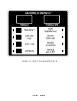
Страница 32: ...13 8 612 Page 22 FIGURE 4 7 AUTO SENTRY S SOLID STATE CONTROL TOUCH PAD...
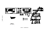
Страница 33: ...13 8 612 Page 23 200EBB546 Ref Drawing FIGURE 4 8 WIRING DIAGRAM...
Страница 53: ...13 8 612 Page 43 PIPING AND MOUNTING GROUP 213EBB810 B Ref Drawing...
Страница 61: ...13 8 612 Page 51 ELECTRICAL GROUP 205EBB810 A Ref Drawing For Parts List Refer to Pages 52 thru 54...
Страница 72: ...13 8 612 Page 62 FIGURE 11 4 REFRIGERATED DRYER FIGURE 11 5 SUCTION PRESSURE GAUGE DRYER INLET AND OUTLET...
Страница 73: ...13 8 612 Page 63 FIGURE 11 6 CONDENSER HEAT EXCHANGER HOT GAS BYPASS FIGURE 11 7 COMPRESSOR REFRIGERATED DRYER...
Страница 77: ...13 8 612 Page 67 INTEGRATED DRYER ASSEMBLY AND PIPING 301EBB810 A Ref Drawing...
Страница 82: ...13 8 612 Page 72 300EBB541 B Ref Drawing...
Страница 84: ......


